OK, I give up. So many amps to build, Sissy Defisit, M25, Vfet, F7, J2 and few others....I am building separate Power supply. Hardly new Idea, but thoght I would start this thread to get ideas for most versatile one.
Will combine ideas from Eric, who shared with me his version and how it works.
Transformer, or Transformers will be wired in with junction blocks as I usually do, in event different voltage is needed on rails. This likely will not be too often, but am making allowance.
This way, cap banks and rectification can be reused. I try to always use 50 volt caps, to allow for possible higher rail voltages, will do same here. Connections to amp will be Power Con parts, ( hopefully have greenlee cutter from tube days in proper size already)connecting cables will be short and fat.
Final bank of caps will be in placed in Amp chassis, as I learned from remote tube amp power supplies I used to build. May even use junction blocks and fasteners to make those final caps moveable as well, may not be necessary since the are in addition to stout banks in power supply chassis.
Intend on dual mono, but with removable transformers would also allow single transformer applications if ever necessary. (Have some big honking SUM-R 1000 VA unit)
Any thoughts or ideas much appreciated, only want to build this thing once!
Russellc
How about an umbilical not so fat that there is a bit of measurable resistance? It can be part of a CRC.
Had not thought of that, but am sort of limited In terms of "fat" by ability to fit in connector.
Russellc
you already said pretty much everything
if possible , go with dual secondaries-two Graetz approach
lesser chance of buzz etc.
Ah, another chance to demonstrate my ignorance on world wide web (is done frequently, but willing to learn...still digesting cascade materials you posted)....can you show such a Schematic example? May tax my few brain cells, but will try.
Russellc
Personally, I would keep the +V supply 0V and the -V supply 0V separate, join the two separate 0V's inside the amp case, I'd add the chassis/ground breaker at that point (CL60 or 100R//100nF).
Two extra CL60's could be added to the 0V's in the PSU chassis if you don't want them to float wrt the chassis.
Two extra CL60's could be added to the 0V's in the PSU chassis if you don't want them to float wrt the chassis.
Any thoughts or ideas much appreciated, only want to build this thing once!
Russellc
I would make CLC instead of CRC if I were in your position. Quieter, less voltage loss, and fancier.
")
BTW, I always wonder if Variac on power line could make sound worse. If not, I would put Variac in the PSU for variable voltage.
Careful, there's no mains isolation with a variac, you still need a transformer for isolation, unless you intend to use both, in that case it would probably be better to buy an oversized multi tap instead.
Yes, I meant to say additional Variac before main xformer. In this configuration, Variac makes sounds bad? One good thing about Variac for me is I can test amps a bit more relaxed way.
Russelc,
Me too. My thoughts for the separate amplifier psu revolve around: i) given the similar power requirements of many of the Nelson Pass designs, why not?; and, ii) to reduce em/rf emissions inside the amplifier case.
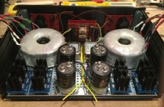
Here is a picture of my work in progress. The transformers are 500 VA Primrose 2x18V, and you can just glimpse the line filters, soft starts and DC blockers in the background.
Each transformer circuit is electrically separate other than common points at the IEC inlet and a single common ground point. Rectified DC will be filtered via CRC through the oh-so-shminky Sikorels (sort of a birthday present) and then out of the case via Powercon32 connectors (they are very slick).
The rectifier bridges (Graetz) fit nicely, although in hindsight I would have been better off with a deeper case (this is a Modushop Slimline 3U x 280mm).
OK, I give up. So many amps to build, Sissy Defisit, M25, Vfet, F7, J2 and few others....I am building separate Power supply. Hardly new Idea, but thought I would start this thread to get ideas for most versatile one.
Russellc
Me too. My thoughts for the separate amplifier psu revolve around: i) given the similar power requirements of many of the Nelson Pass designs, why not?; and, ii) to reduce em/rf emissions inside the amplifier case.
Here is a picture of my work in progress. The transformers are 500 VA Primrose 2x18V, and you can just glimpse the line filters, soft starts and DC blockers in the background.
Each transformer circuit is electrically separate other than common points at the IEC inlet and a single common ground point. Rectified DC will be filtered via CRC through the oh-so-shminky Sikorels (sort of a birthday present) and then out of the case via Powercon32 connectors (they are very slick).
The rectifier bridges (Graetz) fit nicely, although in hindsight I would have been better off with a deeper case (this is a Modushop Slimline 3U x 280mm).
Attachments
Thanks ZM. Nah, no sissies here, I'm just experimenting.
I have read here and there that the line filters can have that mellowing effect, but no experience with these ears. I am going to test both ways to see what sounds better.
They are easy to bypass for testing, and easy to remove if bad for sound. Maybe no filters has more verve or speed?
It feels like kind of a black box exercise though - the filters have virtually no measured impedance, and if one believes the manufacturers performance characteristics the attenuation is quite modest below 80 kHz.
Pass DIY Addict
Joined 2000
Paid Member
I have a few chokes around that I purchased for a different reason that I'm likely to include in my modular power supply.
Right now, I have a single transformer with dual secondaries followed by CRC, then a 3-conductor (+v, 0, -v) umbilical, then inside the amp, the +V splits to each channel. Each channel has its own +V cap. The same happens with the -V, it splits for each channel inside the amp, each channel has its own -V cap. Thus, there are four caps inside the amp, two for each channel (one pos, one neg).
My thinking was that the umbilical might act as a "pseudo" second R, so I'd have something closer to CRCRC before the amp boards. The PSU ripple for my M2 is somewhere near 12-13mV on the last cap inside the amp. I was thinking of re-arranging things so I have transformer-CCL-umbilical-C-amp instead to see what difference this makes. My inductors are ~10A ~50mH.
...My inductors are ~10A ~50mH.
Nice, where did you get them from?
Pass DIY Addict
Joined 2000
Paid Member
They are from microwave ovens. The primary winding will handle ~10A and they measure about 50mH on my meter. I think DCR is near 0R5 - need to measure again with more precise methods. They aren't super pretty to look at, but coat of paint might help that...
Also, don't forget to fuse the primary of your transformer in your modular power supply.
Also, don't forget to fuse the primary of your transformer in your modular power supply.
- Status
- This old topic is closed. If you want to reopen this topic, contact a moderator using the "Report Post" button.
- Home
- Amplifiers
- Pass Labs
- Separate Power Supply for First Watt Amps