Maybe with brackets holding transformers standing up, would have measure, dont think there is enough width.
You can stack the transformers and PSU pcbs with some creativity, shouldn't be too hard to fit a dual mono psu in the 4u case.
You can stack the transformers and PSU pcbs with some creativity, shouldn't be too hard to fit a dual mono psu in the 4u case.
Not even close to enough height for 2 of the transformers I'm using. I will have to look at the 300VA I used in my dual mono F-5, but I don't think they are that much shorter...again, maybe with 5U chassis. I will measure and comment when I get home. The 4U isn't nearly as tall or deep as 5U, quite a difference.
Russellc
Last edited:
Due to advancing age and bad shoulders and elbows I am intending to go dual mono-bloc - with external power supply. [Also it would be good to have a free standing PS so that I could use it with other amps without even moving it!]
In fact is there any good reason why I should not have mono-bloc power supplies?? [I already have an ample supply of 7mm alloy sheet with which to build a 4 bloc stereo set up.]
In fact is there any good reason why I should not have mono-bloc power supplies?? [I already have an ample supply of 7mm alloy sheet with which to build a 4 bloc stereo set up.]
even better - helicopter - transported amplifiers;
that way you can carry 100 channels in one case

that way you can carry 100 channels in one case


Question on picking 4N35 optocoupler
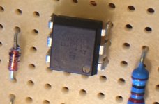
Hopefully I did not mess up, just getting ready to solder in the optocoupler and was looking close at the picture in Teabag's blog to make sure I oriented them properly and noticed a difference between his and mine.
Tea's, like mine have printing on the top , 4N35, with V 33924 inscribed underneath. Looking with a magnifier, I noticed mine said 4N35 as well, but the inscription underneath was V 32724.
mine is this part:
4N35 Vishay Semiconductors | Mouser
There a a few variations, so I looked at the specs. A few are SMD type, but several are DIP 6 type. Most of the specs are similar, most having a power dissipation of 150mW, but the one I chose, first on the list has a dissipation of 70 mW. There were a few other minor variations as well.
Is this part sufficient? Or should I have selected one of the others? I was just about to solder them in when I noticed this and thought I better check!
Thanks for your thoughts on this. I should be able to finish wiring tomorrow.
Thanks in advance,
Russellc
How are people doing with DC offset and having to adjust R6 and R7?
Russellc
I have not done anything yet. When you install these resistors install them high so you will not have to remove boards to hook up different resistors if necessary. If you leave enough leads of the resistors showing you can clip the resistor out and use the leads left to install another value resistor if necessary or even parallel another resistor. I have -85mv which is not a big concern of mine and honestly I have not quit listening long enough to correct it. Yours could possible adjust to zero with no problem. I like Zen's answer about 4N35.
And get busy Russell, I want to hear your impressions!
4n35 is 4n35 is 4n35
Ahhh, thank you Zenmod! Solder gun heating up.
Russellc
I have not done anything yet. When you install these resistors install them high so you will not have to remove boards to hook up different resistors if necessary. If you leave enough leads of the resistors showing you can clip the resistor out and use the leads left to install another value resistor if necessary or even parallel another resistor. I have -85mv which is not a big concern of mine and honestly I have not quit listening long enough to correct it. Yours could possible adjust to zero with no problem. I like Zen's answer about 4N35.
And get busy Russell, I want to hear your impressions!
I thought of leaving long leads as well, I also have some of these little sockets I thought I might use in those locations:
You just snap off what you want, 1, 2, whatever and solder in the hole.
Attachments
![IMG_4193[1].jpg](/community/data/attachments/479/479645-e17a3f3f7570c1711aa7984058f3e3f0.jpg?hash=4Xo_P3VwwX)
-85mv
So you still have both 47K resistors in R6 and R7 positions? What is your offset?
Since I used Tea's boards and verbatim parts he used, I used the 47k at R6 but like Tea did, put 53K at R7. Should know a little later!
Russellc
See post #778 and #781 of mighty Zen's. He likes + or - 30mv but also in post #781 seems say that -85mv is not unacceptable. I have plans of lowering one day but I see it as not something to lose sleep over. I have had a Gainclone build of old with this much offset positive for years with no problem. I will get around to lowering it one day. It is 85mv not .85mv as I incorrectly stated in an earlier post. To put it in perspective it is in miilivolts which are very very small amounts. If my speakers were popping on turn on or turn off I would be concerned.
Last edited:
To those building with Teabag's boards and predrilled store deluxe chassis
Normally, when fitting the mosfets to the heat sink with the F-6 store boards and the BA-3 store boards (w/ 3 pairs per side) I usually bend the mosfet legs right at the point where the thinner tip portion becomes the slightly wider part of the leg. I just mounted the M-2 boards onto the mosfets and I had a slight (very,very slight) problem, the board wouldnt go quite high enough for the screws to match the threaded studs. No biggie, just bend them a slight amount before the place where the thinner part becomes thicker, letting the board ride just a smidge higher.
If you are not using the predrilled store chassis/heatsinks, carry on. If you are having trouble picturing what I am talking about, check out a pick of the sort of mosfets the Firstwatt clones use, the three legs come out of the device slightly wider, then the second half of the leg becomes thinner. Just bend a very slight amount before this change up, not right on it.
I just had to straighten the legs, and rebend with a small precision set of needle nose with the mosfets still mounted. Just take your time and dont force anything.
Russellc
- Home
- Amplifiers
- Pass Labs
- Official M2 schematic