Aleph 5
Thanks a lot for many of helpful remarks!
Concerning the missing junction between R17, R19 etc: it is ok on the PCB. Also the R16 shown as 4K75 in the schematics is correctly marked on the PCB as 1K5. (In case you didn't notice)
So it seems that I go for the IRFP240 after all. But I will buy the 2sj313 like you both suggest. Will the R13 and R17 mods be ok when changing to 2sj313?
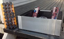
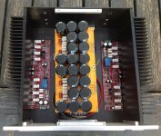
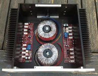
Here are some pics showing status at the moment!
Thanks a lot for many of helpful remarks!
Concerning the missing junction between R17, R19 etc: it is ok on the PCB. Also the R16 shown as 4K75 in the schematics is correctly marked on the PCB as 1K5. (In case you didn't notice)
So it seems that I go for the IRFP240 after all. But I will buy the 2sj313 like you both suggest. Will the R13 and R17 mods be ok when changing to 2sj313?
Here are some pics showing status at the moment!
Attachments
yup
also - ref to your schm , change to R9 to something higher - say 220K to 330K
dunno what drek is R4 - leave it out completelly
remove R5 , increase R6 to same as R9
put 3uF3 to 10uF elko across D5
be sure that all output source resistors are 1R , and take note that Iq as from PL is 500mV across each of them ......... if your heatsinking is allowing that
Aleph 5 mod
Starting with the R4 - it is the unbalanced input as also shown in the original schematic. Why it exists in the original in the first place, I don't know...
You suggest changing R9 and R6 into > 200K... If I am correct, is it really necessary to have an input impedance more than, say 100K?
I see that the R5 is superfluous, and putting a cap across D5 seems wise.
I have used 1R5 for all source resistors, am I in trouble? I thought it might reduce the quiescent current somewhat, which is a good idea for my relatively modest heatsinks. But with your suggested R17 mod, Iq can now be adjusted.
Anyway, I will give my heatsinks as much as is safe. Will 50 degrees C be too high working temperature for the heatsinks?
Attachments
")
M0rten,
I case you haven't seen this yet, Mr. Pass has written recently about some mods
to the Aleph design, including the use of 2sj313:
http://www.diyaudio.com/forums/pass-labs/267857-aleph-design-reloaded.html#post4184920
Cheers,
Dennis
I case you haven't seen this yet, Mr. Pass has written recently about some mods
to the Aleph design, including the use of 2sj313:
http://www.diyaudio.com/forums/pass-labs/267857-aleph-design-reloaded.html#post4184920
Cheers,
Dennis
establishing
I have a doubt, where should I connect the GND of the speaker terminal in the above PCB? I can see only the speaker + terminal.
Can I connect it to the RCA/XLR ground?
---
Best regards,
BP
I have a doubt, where should I connect the GND of the speaker terminal in the above PCB? I can see only the speaker + terminal.
Can I connect it to the RCA/XLR ground?
---
Best regards,
BP
I think power supply ground is a good place for speaker ground. Good luck!
Aleph 5 another build
Hello guys,
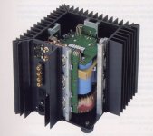
I'm planning to build an Aleph5 (enough output power for my Totem SKY speakers).
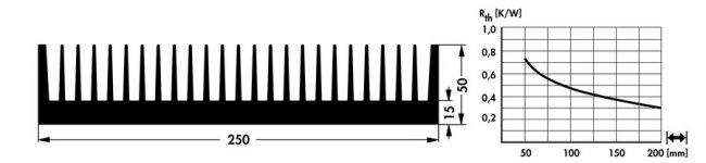
The design will sticky adhere to the Pass one, picture attached, so 4 heat sinks (one per side). Being the heat dissipation a great cause of concern, I run into some searching and finally have selected the SK622 from Fischer Elektronik, Width 250mm, Height 50mm, base plate 155mm, picture attached.
Manufacturer data indicates a Rth of 0.3°C/W at a length of 200mm, I'm considering to have a length of 250-300mm each.
Considering 150 W per channel continuous heat dissipation, spreaded over two heat sinks (75-80W) the temperature increase should be 25 °C. Heat sink temperature close to 50 °C.
The power transformer selected from Toroidy (Polish manufacturer) 800-1000VA. Any DIY'er feed back about Toroidy?
Concerning the PCB, I'm thinking to design 1 PCB (4 layers) for the fron-end and 4 PCB (2 layers) for the output devices.
Tips greatly appreciated
thank you
Hello guys,
I'm planning to build an Aleph5 (enough output power for my Totem SKY speakers).
The design will sticky adhere to the Pass one, picture attached, so 4 heat sinks (one per side). Being the heat dissipation a great cause of concern, I run into some searching and finally have selected the SK622 from Fischer Elektronik, Width 250mm, Height 50mm, base plate 155mm, picture attached.
Manufacturer data indicates a Rth of 0.3°C/W at a length of 200mm, I'm considering to have a length of 250-300mm each.
Considering 150 W per channel continuous heat dissipation, spreaded over two heat sinks (75-80W) the temperature increase should be 25 °C. Heat sink temperature close to 50 °C.
The power transformer selected from Toroidy (Polish manufacturer) 800-1000VA. Any DIY'er feed back about Toroidy?
Concerning the PCB, I'm thinking to design 1 PCB (4 layers) for the fron-end and 4 PCB (2 layers) for the output devices.
Tips greatly appreciated
thank you
Attachments
two of these heatsinks are good for 150W of heat, no doubt
Toroidy is good , according to experience of Greedy Boyz - take their audio line and note that Donut is for A class amp
4 layers for FE pcb - you're making pcb for shooting da thing in orbit?
there is handful of big parts , not zillion smd ones ...... you can do it right even on half layer ........
think Moto Guzzi ..... not Space Shuttle
Thanks!
yes the FE board can be easily done with two layers, the 4 layers idea came in order to keep the signal tracks in the inner layers and to dedicate the outer layers to the power (Vdd, Vss, GND and output).
anyway the Fischer heatsinks SK622 are quite difficult to source in Italy and are very costly!!!!
about 300€ the bar 1 meter length
yup
also - ref to your schm , change to R9 to something higher - say 220K to 330K
dunno what drek is R4 - leave it out completelly
remove R5 , increase R6 to same as R9
put 3uF3 to 10uF elko across D5
be sure that all output source resistors are 1R , and take note that Iq as from PL is 500mV across each of them ......... if your heatsinking is allowing that
Capacitor in parallel to D5 (Z5 on original schematic) better NP or electrolytic?
Also, ina thread from Pass, he suggested to also put a capacitor in parallel to the other zener (Z1,Z2 and Z3,Z4) value between 1 and 4,7uF
- Status
- This old topic is closed. If you want to reopen this topic, contact a moderator using the "Report Post" button.
- Home
- Amplifiers
- Pass Labs
- Questions about the Aleph 5