Yess... It certainly could be "detail bettered".. so what ?
Regardless, It's been working Absolutely perfectly.. since 2016.
Zero amp sounds with Ears as far into my Tannoy cones as I can get them; full volume .. no volume , power on .. power off ... there is only dead silence.
I find that Astounding and unprecedented actually... despite ' fooling ' with audio 'stuff' since '67
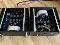
Heatsinks are Too big imo.. 9" x 10" with 2 3/4 " deep fins.
Amp barely gets past body temp (palpably warm) even after hours of use.
Haven't even bothered to read the temp as result.
Resultant Case is Wayyy overkill/size ..as result of those sinks and the Looong F6 pcb.
One day I'll rebuild / downsize it.
But then there is the: "if it ain't Broke.. don't fix it ' point of view")
Regardless, It's been working Absolutely perfectly.. since 2016.
Zero amp sounds with Ears as far into my Tannoy cones as I can get them; full volume .. no volume , power on .. power off ... there is only dead silence.
I find that Astounding and unprecedented actually... despite ' fooling ' with audio 'stuff' since '67
Heatsinks are Too big imo.. 9" x 10" with 2 3/4 " deep fins.
Amp barely gets past body temp (palpably warm) even after hours of use.
Haven't even bothered to read the temp as result.
Resultant Case is Wayyy overkill/size ..as result of those sinks and the Looong F6 pcb.
One day I'll rebuild / downsize it.
But then there is the: "if it ain't Broke.. don't fix it ' point of view
I agree, I have experimented with the bias on my F6 and "more is better" does not always apply.Bias is capably set . I forget where tho.. It has been 6 years.
F6 only runs warm, as opposed to Hot .
Note that there IS a sweet spot and it's definitely not at the highest bias point,
Experiment.. and find what pleases You.
If the bias goes too high (above 700mv from memory), I found that the sound got harsh and I did not like it.
However, what was harsh to me might be more detailed to someone else!
Subject to the capability of each build to stay at a reasonable temperature it's worth experimenting.
The sweet spot for the output bias will depend on the type of Mosfets being used. The IRFP240 (standard) may indeed have a lower preferred bias current. Experience with other amps using these devices suggests about 1.6A may be plenty.
On the other hand, the FQH44N10 prefers higher Vds and bias current. Mine are running with 26V rails and 1.85A bias current. They are built to handle higher power dissipation. Proper thermal attachment is necessary of course. I prefer aluminum oxide & goop.
On the other hand, the FQH44N10 prefers higher Vds and bias current. Mine are running with 26V rails and 1.85A bias current. They are built to handle higher power dissipation. Proper thermal attachment is necessary of course. I prefer aluminum oxide & goop.
What is the formula for calculating the amperage based on the volts across the 0.47 resistor?The sweet spot for the output bias will depend on the type of Mosfets being used. The IRFP240 (standard) may indeed have a lower preferred bias current. Experience with other amps using these devices suggests about 1.6A may be plenty.
On the other hand, the FQH44N10 prefers higher Vds and bias current. Mine are running with 26V rails and 1.85A bias current. They are built to handle higher power dissipation. Proper thermal attachment is necessary of course. I prefer aluminum oxide & goop.
Mike, what kind of temperature are you seeing at the second pin of the IRFP240 MOSFET when you are running that .62 voltage?Good idea, I may mess with that at some point. Let me know if you figure out what your amp's sweet spot is. I have mine at .620 across the .47 source resistor. 18vac secondaries.
Ohms law I - V/RWhat is the formula for calculating the amperage based on the volts across the 0.47 resistor?
right under 65 degrees celcius that 6L6 recommends as the stopping point.Mike, what kind of temperature are you seeing at the second pin of the IRFP240 MOSFET when you are running that .62 voltage?
If'n I'm understanding balanced operation, I can wire this up like the ACA except tieing the negative outputs together to ground as the F6 doesn't invert polarity.
Anyone mind checking my thinking?
XLR Pin 1 goes to ground.
XLR Pin 2 goes to + input on the + (or Right) board
XLR Pin 3 goes to + input on the - (or Left) board
- input on both boards are left floating unless I have RCA jacks to tie them to.
"+" output on +/R board goes to right + speaker post
"+" output on -/L board goes to left + speaker post.
Both - speaker posts get tied together to ground.
Anything I'm missing or overlooking before I do something stupid?
ha! I'm a total silly billy. Thanks for the hint. Only have to wire in the XLR jack as I outlined and give it a go. Might be able to wire it up temporarily to give it a quick try tomorrow night. No silliness with the speaker outputs as they are already tied to ground via the PSU connection. Time to get out the drill.I suggest you draw out the full balanced circuit of the 2 amp 'boards' before ...
Umm, for an amplifier to work as a balanced operation, both your F6's left and right channels are used to produce just the single balanced output between each amp channel's +ve terminals - if so, you will need another complete 'balanced' F6 amplifier to produce a stereo sound.
Also, if you want the single F6 amp to produce just the one balanced output, either the left or right amp's channels needs to receive the inverted signal from the preamp - this shouldn't be any problem but, and a significant BUT, is that the basic F6 amp circuit doesn't include the ability to operate with a balanced signal input so you would need to add a "balanced -> unbalanced" converter stage to the amp's input - again, this isn't all that difficult as quite a few circuits, and possibly kits, are available but it doesn't sound like this is quite what you want to do ...
Also, if you want the single F6 amp to produce just the one balanced output, either the left or right amp's channels needs to receive the inverted signal from the preamp - this shouldn't be any problem but, and a significant BUT, is that the basic F6 amp circuit doesn't include the ability to operate with a balanced signal input so you would need to add a "balanced -> unbalanced" converter stage to the amp's input - again, this isn't all that difficult as quite a few circuits, and possibly kits, are available but it doesn't sound like this is quite what you want to do ...
Umm, 2 chassis, 4 F6 boards, 2 inputs, 2 outputs. That should cover. Just trying to make sure I'm connecting to signal ground properly. Hoping to get one of these jimmied up tonight to see how the sonics change. Still have to wire up the PSU for the 2nd one.Umm, for an amplifier to work as a balanced operation, both your F6's left and right channels are used to produce just the single balanced output between each amp channel's +ve terminals - if so, you will need another complete 'balanced' F6 amplifier to produce a stereo sound.
Also, if you want the single F6 amp to produce just the one balanced output, either the left or right amp's channels needs to receive the inverted signal from the preamp - this shouldn't be any problem but, and a significant BUT, is that the basic F6 amp circuit doesn't include the ability to operate with a balanced signal input so you would need to add a "balanced -> unbalanced" converter stage to the amp's input - again, this isn't all that difficult as quite a few circuits, and possibly kits, are available but it doesn't sound like this is quite what you want to do ...
But back to the original question, appreciate the help. Drawing the board connections out and checking a few points for continuity got me to realize almost everything is already connected to ground. Just have to connect the XLR ground to the nearest signal ground point (which could be a RCA jack per a ZM post I found).
Attachments
Last edited:
Have you got a Variac? It saves a lot of potential mistakes - I know this well!
Surprisingly, for some balanced amp connections, it's the grounding systems that produce a lot of problems like hum, ground returns, etc - you might check-out the idea of 'floating the balanced signal ground point' in case you need it (Bryson, etc) - suggest you try the 3 leds mod
All the best with your project, it's looking very good.
thanks, jameshiilj.
No variac. I've been doing audio as a hobby for 20+ years and have gotten very lucky. One of those items I really need to get but as much as I move around, I keep taking the chance of not having one. I dream of having a test bench setup one of these days. Currently (heh), both boards in the one chassis power up and bias up just fine. So I have high hopes (waiting to be dashed on the rocks of a short to ground, heh.)
Speaking of grounding, thanks for the tip on the floating. Hoping to try amplifying tonight. If not then this upcoming long weekend. Could be just fine and I'm overthinking it. But I will look into the floating idea. Usually when things work just fine, one learns less and you have to make extra effort via other avenues.
- Home
- Amplifiers
- Pass Labs
- F6 Illustrated Build Guide