
good .......
for building level of self-confidence, so next time you're going to use eyes and brain, before keyboard
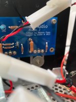
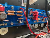
Did use brain and eyes before keyboard; maybe not long enough! Checked continuity. Checked voltages. Basically I just lucked out. If I hadn't jostled r28 in the process of chasing down the problem and noticed that it was misaligned I'd still be scratching my head and sending you pictures. Happened to have a spare 4.7k resistor; now all is back to fine.
On a side note ZenMod,. You mentioned a while ago that you were getting or had just gotten a CNC machine. If so, have you posted your experiences with it anywhere?
On a side note ZenMod,. You mentioned a while ago that you were getting or had just gotten a CNC machine. If so, have you posted your experiences with it anywhere?
CNC - have all custom parts/plates made, everything else I need are industrial pieces, so piece of cake
need time
as with all other things, when I get itch to actually need "somethingsomething" to make with my own CNC, I'll make it pronto

need time
as with all other things, when I get itch to actually need "somethingsomething" to make with my own CNC, I'll make it pronto
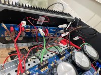
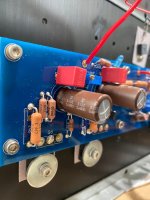
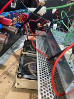
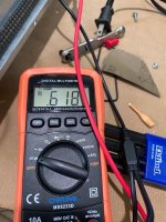
I have a question regarding the bias adjustment. I had everything wired up and both the bias adjustment and offset adjustment were working fine. I had not looked at it in awhile and went back to see how high I could get the bias with my Noctua fans keeping the heatsink cool. Unfortunately, I did not take the time to make sure I knew what I was doing and I started adjusting the bias pot thinking it was the offset pot. Of course turning the pot had no impact on the offset. I turned it quite a bit in both directions seemingly without effect. In the meantime, I had the heatsink displaced from the fans and it reached about 132 F. Once I realized my mistake, I looked at the bias and it was at .618 volts (about 1.3 Amps). Turning the bias pot now appears to have no impact on the bias. Could I be at an insensitive setting on the pot? Which direction should make the bias go up or down? Previously, I had gotten the bias up to 1.17 Amps. I could live with 1.3 Amps, but I wonder if something is wrong. Shouldn't I be able to get it higher? Right now it doesn't seem to go higher or lower by much, but maybe I just need to turn the pot a lot? If I put the fans back under the heatsink would that impact how high it would go? The offset sets without any problem when I turn the appropriate pot.
Thanks for any insight anyone can provide.
Thanks for any insight anyone can provide.
Attachments
-
 IMG_1444.jpg475.7 KB · Views: 27
 -
 IMG_1445.jpg422.6 KB · Views: 26
 -
 IMG_1446.jpg501.4 KB · Views: 24
 -
 IMG_1447.jpg383.1 KB · Views: 22
 -
 IMG_1448.jpg366.2 KB · Views: 22
 -
 IMG_1455.jpg623.4 KB · Views: 22
 -
 IMG_1449.jpg390 KB · Views: 22
 -
 IMG_1456.jpg505.3 KB · Views: 23
 -
 IMG_1457.jpg513.9 KB · Views: 22
 -
 IMG_1458.jpg383.9 KB · Views: 19
 -
 IMG_1459.jpg399.5 KB · Views: 20
 -
 IMG_1460.jpg638.7 KB · Views: 26
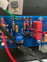
You could get a second multimeter (something cheap). Then, simultaneously, monitor the DC offset at the binding post and the bias across one of the 0.47 ohm, 3W resistors. That'll clear up the confusion. You'll figure out that adjusting the DC offset, for example, will also change the bias slightly, and vice versa.
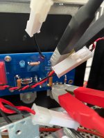
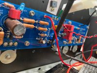
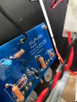
The trimpots are multiturn... I think 20 turns from memory, but it could be less. You will feel the end of travel in either direction when adjusting them. Consider getting a spare trimpot and practising to get the feel for it. There's no dead spot along the adjustment travel. Bourns have multi-wiper contacts (see photo), and should be reasonably reliable.
I think you'll be okay... just try again but make sure the probes are attached where they should be, and take it easy... and do not be afraid to spin the trimpot screw a lot. However, if there's no change at all, then the trimpot's probably damaged.
It is very unlikely that the excessive heat dissipation, as you reported, caused any damage... but I'd recommend a larger case if you want to get the best out of Aleph J... it likes to be run at high bias... 2A is a good setting 🙂

Thank you, Extreme_Boky. That is helpful. I will play around with the trimpot. I do recall hearing a clicking sound emanating from it. It may well be that I broke something in it. My spinning the trimpot a lot should tell me if it is broken or not.
The clicking sound is an end-of-travel "warning". That does not mean the trimpot is damaged or faulty. You should be good.
So, I turned the bias pot from its first click cw to its first click ccw. I counted 30 1/2 turns. I put it halfway between the two and turned on the amp. Turning ccw worked to reduce the bias. Turning cw, I got it up to .630 and then further turning did not increase the basis. It fell slightly to .625 and I could get it no higher. I stopped turning at the second click. Any ideas on why the bias will not get any higher than .625?
With 0.625V across each 0.47 ohm resistor, you are measuring 1.33A of current per each MOSFET pair. That means the total bias for one AMP PCB is 2.66 A, which is too high.
Combined (two AMP PCBs), you'll be dissipating around 250W - and that is too hot for the case you are using at the moment.
You could start with 0.4V bias, as measured across each 0.47 ohm resistor.
Combined (two AMP PCBs), you'll be dissipating around 250W - and that is too hot for the case you are using at the moment.
You could start with 0.4V bias, as measured across each 0.47 ohm resistor.
My fans are keeping it somewhat cooler. At .610 the heatsink stabilizes at about 127 F. I am thinking of backing it down to about 120 F. Does that seem reasonable?
Whatever makes you comfortable.
120F is fairly hot. The monoblock build is a great idea - just keep in mind that you are still only using a single heatsink per each AMP PCB, so I'd recommend staying at a total dissipation per MOSFET of around 25W. With 24V DC rails, that puts you at around 470mV of bias, measured across each 0.47 ohm resistor.
120F is fairly hot. The monoblock build is a great idea - just keep in mind that you are still only using a single heatsink per each AMP PCB, so I'd recommend staying at a total dissipation per MOSFET of around 25W. With 24V DC rails, that puts you at around 470mV of bias, measured across each 0.47 ohm resistor.
- Home
- Amplifiers
- Pass Labs
- Aleph J illustrated build guide