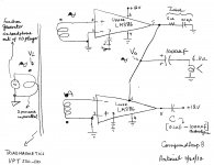
I was not happy with the performance of the simple differential voltmeter which was based on power transformers as I described it earlier. It was inaccurate in the frequency range of 30 - 150 Hz. Instead, I assembled on a proto board a classical differential amplifier using a 741 Op Amp which I powered with 2 rechargeable 9 Volt batteries. The top part of the attached file CompoundAmp A4.pdf shows the schematic of this diff amp of voltage gain ~10. Its output fed the AC multimeter. The bottom part of the file shows the test setup for the Compound Power Amplifier [CPA] which I then used to accomplish the following objectives:
Results
The Transconductance [Gm] of TCA in the 30 -150 Hz range was calculated as follows: Io = Va/0.5 Ohms or 150 mV/0.5 Ohms = 300 mA. Note that it is already amplified by the diff amp by a factor of 10. And Gm =300 mA/300 mV in = 1 A/Volt.
The first two objectives were met. To be continued...
- Calibrate the diff amp and the CPA components with 4 and 8 Ohm non-inductive power resistors [20% tolerance]
- Measure impedance in the frequency range of 30 Hz - 150 Hz for the woofer in the A/D/S L-730 loudspeaker
- Generate additional graphs which shed light and explained the operation of the CPA.
Results
- Z = 4 Ohms: Va = Vb = 150 milli Volts. Average Vsp4 = 1.19V +/-0.3% . It was a straight line in the range of 30-150 Hz.
- Z= 8 Ohms: Va = Vb = 150 milli Volts. Average Vsp8 = 2.48 V +/-0.3%. It was a straight line in the frequency range 30 - 150 Hz. Note that the value of Vsp8 was roughly double that of Vsp4 as expected.
- Z =woofer impedance. Va = Vb = 150 milli Volts. The second attached file Compound Amp A4 Impedance.pdf shows the impedance of the woofer in the 30 -150 Hz range. The voltage Vsp [shown] mirrors exactly the impedance. I also superimposed the reference calibrators Vsp4 and Vsp8. A maximum impedance of ~9.4 Ohms was measured at the woofer's resonance frequency of 45 Hz. A minimum impedance of ~4.3 Ohms was measured in the range of 90 - 100 Hz.
The Transconductance [Gm] of TCA in the 30 -150 Hz range was calculated as follows: Io = Va/0.5 Ohms or 150 mV/0.5 Ohms = 300 mA. Note that it is already amplified by the diff amp by a factor of 10. And Gm =300 mA/300 mV in = 1 A/Volt.
The first two objectives were met. To be continued...
Attachments
The attached file CompoundAmp A4 Impedance1.pdf shows two graphs which explain the individual operation of the VSA and TCA [30-150 Hz] in the Compound Power Amplifier. What is each amplifier doing as the impedance of the woofer changes with frequency? I collected 18 data points for Vo which is the output of TCA, and 18 data points for the Joint Output after the switch is closed to integrate them to CPA. Please note the definition of Vo and Joint Output per the setup schematic of the previous post:
In the CPA, Fig. 3 shows that TCA was putting out a constant current as inferred from the constant voltage Va of average value = 150 milliVolts +/-0.4%. By contrast, the current [from TCA] flowing through the loudspeaker as measured by Vb across 0.5 Ohms in series with it was inversely related to the impedance of the woofer. At each frequency point of measurement in Fig. 3, the numerical difference between Va and Vb is the offset current that the VSA soaked up or siphoned off the loudspeaker. Why? Had the VSA not done so, the Joint Output would have violated its expected constant output of 1.44 V imposed by its intrinsic design.
I'll distill the learnings and conclusions in an upcoming post. In the interim, dwell on the results, ask for clarification if needed, and add your comments.
To be continued..
- Vo = Va + Vsp + Vb . Holds true for the stand alone TCA and for CPA.
- Joint Output = Vsp + Vb only for CPA.
In the CPA, Fig. 3 shows that TCA was putting out a constant current as inferred from the constant voltage Va of average value = 150 milliVolts +/-0.4%. By contrast, the current [from TCA] flowing through the loudspeaker as measured by Vb across 0.5 Ohms in series with it was inversely related to the impedance of the woofer. At each frequency point of measurement in Fig. 3, the numerical difference between Va and Vb is the offset current that the VSA soaked up or siphoned off the loudspeaker. Why? Had the VSA not done so, the Joint Output would have violated its expected constant output of 1.44 V imposed by its intrinsic design.
I'll distill the learnings and conclusions in an upcoming post. In the interim, dwell on the results, ask for clarification if needed, and add your comments.
To be continued..
Attachments
Last edited:
Here's an interesting connection which came to mind. But first note that any gain device [including TCA] is intrinsically imperfect because the current flowing throught it and the voltage cross it vary as it delivers power to the load [paraphrase per Nelson Pass]. The answer to suppressing voltage variation is the technique of cascoding. As the impedance of the woofer varies, the voltage across the internal devices of TCA vary accordingly. In the CPA, the voltage variations [Vo for TCA only]are sequestered as seen in Fig. 2 of CompoundAmp A4 Impedance1.pdf above. The net result of Vo =1.59 V suggests that the VSA acted as a cascoding device to TCA. Thus, the intrinsic imperfection in TCA due to voltage variations across it is substantially reduced by this pseudo cascoding which is a plus for the overall performance of CPA.
In posts 19 and forward, the TCA was the sole contributor of output current to the loudspeaker. I noted that some of this current was shunted by the VSA when the impedance of the woofer [as the working example] increased above its minimum value of ~4 Ohms at 95 Hz to ~9 Ohms at its resonance frequency of 45 Hz. Clearly, the VSA wasted "valuable" output power, and an attendant fraction of the sonic print of TCA. This maybe/is unacceptable. The numerical value of 4 Ohms above was preset with the 25 Ohm pot across the secondary winding feeding the VSA. This pot adjusted Ei and set the output voltage Eo of VSA to buck exactly the output voltage Vo from TCA. In the upcoming post, I will increase the value of Ei and hence Eo such that Eo bucks exactly the value of the votage Vo from TCA at the resonant frequency of the woofer of 45 Hz. In this new experiment, TCA is the sole contributor of current to the woofer at its resonance frequency. And will not waste any of its valuable current in the VSA as long as the impedance does not rise above 9 Ohms. But; and there is inevitably one. As the impedance of the woofer rolls downhill from resonance [on either side of 45 Hz], the VSA begins to contribute more output current to the loudspeaker; in effect diluting the contribution [and sonic print] of TCA.
To be continued..
To be continued..
This is a continuation of post#24. The attached file CompoundAmp A4Fig1.pdf shows the working schematic for this experiment and its following procedure:
The voltage drop across the woofer due to VSA only and CPA had a similar shape. This means the woofer is under the control of the VSA unit [for damping and %THD etc.]. For practical purposes, the voltage drop across the woofer in the test frequency range is much flatter than due to TCA only operation. The output power invested in the woofer by CPA has changed relative to that from TCA only operation. Thus, the tonal balance of the subwoofer must adapt and change accordingly. It did, and got louder by comparison with TCA only operation. Figure 3 shows the variation of voltage drop across the sense resistors [0.5 Ohm] as a function of frequency. This voltage drop [mV] mirrors the current flowing through the sense resistors. The voltage Va mirrors the current contribution of TCA only in CPA. It was constant at 136 mV in the test frequency range. The voltage Vb mirrors the current flowing through the loudspeaker [woofer] from the sum contributions of TCA and VSA. Note that Va = Vb at 45 Hz; because I adjusted it that way at the outset of the experiment. Thus the contribution of TCA to the current flowing through the woofer at 45 Hz is 100% [0% from VSA] and expresses its sole sonics. The VSA component begins to contribute current flow through the woofer on either side of the resonance frequency. The peak contribution of current from the VSA occured at the minimum woofer impedance of 95 Hz. This contribution from the VSA component was equal to the mirror value of 134 mV [shown as the symbol delta] . Clearly, the TCA and VSA in CPA each contributed ~50% current through the load. This 1:1 blend ratio is believed to express each of the individual sonic contributions of TCA and VSA in the same woofer. Thus, the varying impedance of the woofer has enabled 120 [150 Hz -30 Hz] different blend ratios with their attendant distinct sonic signatures.
The loudspeaker was louder at this adjustement [max impedance at 45 Hz] than at the previous adjustment of low impedance [earlier post at 95 Hz]. The sound of music flowing out the loudspeaker was fully satisfactory. The woofer region was pronounced [TCA contribution] and articulate . I need to do more listenning.
To do experiment:
- Open Switch and measure the voltage drop across the loudspeaker's woofer Vls as a function of frequency. Find the maximum voltage which mirrors the maximum woofer impedance at its resonance frequency; in my case at 45 Hz. Stay at this frequency and its maximum voltage.
- Adjust the output voltage of VSA [Eo] with the potentiometer [25 Ohms] to equal the value of Vo'
- Close Switch. The voltage drop across the loudspeaker Vls stays constant. This Compound Power Amplifier [CPA] is adjusted to continue this experiment.
The voltage drop across the woofer due to VSA only and CPA had a similar shape. This means the woofer is under the control of the VSA unit [for damping and %THD etc.]. For practical purposes, the voltage drop across the woofer in the test frequency range is much flatter than due to TCA only operation. The output power invested in the woofer by CPA has changed relative to that from TCA only operation. Thus, the tonal balance of the subwoofer must adapt and change accordingly. It did, and got louder by comparison with TCA only operation. Figure 3 shows the variation of voltage drop across the sense resistors [0.5 Ohm] as a function of frequency. This voltage drop [mV] mirrors the current flowing through the sense resistors. The voltage Va mirrors the current contribution of TCA only in CPA. It was constant at 136 mV in the test frequency range. The voltage Vb mirrors the current flowing through the loudspeaker [woofer] from the sum contributions of TCA and VSA. Note that Va = Vb at 45 Hz; because I adjusted it that way at the outset of the experiment. Thus the contribution of TCA to the current flowing through the woofer at 45 Hz is 100% [0% from VSA] and expresses its sole sonics. The VSA component begins to contribute current flow through the woofer on either side of the resonance frequency. The peak contribution of current from the VSA occured at the minimum woofer impedance of 95 Hz. This contribution from the VSA component was equal to the mirror value of 134 mV [shown as the symbol delta] . Clearly, the TCA and VSA in CPA each contributed ~50% current through the load. This 1:1 blend ratio is believed to express each of the individual sonic contributions of TCA and VSA in the same woofer. Thus, the varying impedance of the woofer has enabled 120 [150 Hz -30 Hz] different blend ratios with their attendant distinct sonic signatures.
The loudspeaker was louder at this adjustement [max impedance at 45 Hz] than at the previous adjustment of low impedance [earlier post at 95 Hz]. The sound of music flowing out the loudspeaker was fully satisfactory. The woofer region was pronounced [TCA contribution] and articulate . I need to do more listenning.
To do experiment:
- Use a TCA of low output impedance [Zo]. For example; load the parent TCA [high Zo] used above with an 8 Ohm non-inductive power resistor [for example] to convert it to TCA'. Use TCA' only, and also with the same VSA to drive the woofer of A/D/S/ L-730 in experiments like I did above.
Attachments
To do experiment:
To be continued...
- Use a TCA of low output impedance [Zo]. For example; load the parent TCA [high Zo] used above with an 8 Ohm non-inductive power resistor [for example] to convert it to TCA'. Use TCA' only, and also with the same VSA to drive the woofer of A/D/S/ L-730 in experiments like I did above.
I d like to delay the above experiment in favour of the following one which is in progress:
- Threshold S/150 is a stereo, and an ideal voltage source amplifier [VSA]. The right channel [Rch] will be used exactly like I have done in the above experiments. It has a low output impedance Zo of <100 milliOhms [or VSA-Zo0R]. By contrast, I inserted an 8 Ohm non-inductive power resistor [20 W] in series with the output of the left channel [Lch; or VSA-Zo8R]. Both channels were compounded as shown in the attached file CompoundAmp A5.pdf. This new diagram is like the other ones I showed in previous posts; except that VSA-Zo8R [Lch] has replaced TCA.
Attachments
Last edited:
A Compound Power Amplifier
Objective: Mate a voltage source amplifier [VSA] having a finite output impedance [for example 8.5 Ohms] with another ideal VSA having a ~zero output impedance.
Outcome: A Compound Power Amplifier [CPA] having an ideal ~zero output impedance and the performance of the VSA having the finite output impedance. Specific performance will follow as experimental data are presented.
The time is here to report the findings of the above experiment. I'll stream all of the information over several posts. Ideally, one may wish to print the attached files to connect with the text in the posts. The schematic in attached file CompoundAmpA5a.pdf is the same as the one in the previous post. Please note in this schematic the nodes [Vo1, Vo2, Vo3, Va, Vb, and Vsp] used to generate a graphical performance of the voltage source amp of output impedance equal to 8.5 Ohms or [VSAZo8.5R]. The loudspeaker is an 8 Ohm un-enclosed 15 inch musical instrument which is bolted to a joist of the ceiling in the lab. This speaker is still supplied my MCM Electronics.
Do the following in the next step in preparation for closing Switch A to make the Compound Power Amplifier [CPA].
To be continued...
- Threshold S/150 is a stereo, and an ideal voltage source amplifier [VSA]. The right channel [Rch] will be used exactly like I have done in the above experiments. It has a low output impedance Zo of <100 milliOhms [or VSA-Zo0R]. By contrast, I inserted an 8 Ohm non-inductive power resistor [20 W] in series with the output of the left channel [Lch; or VSA-Zo8R]. Both channels were compounded as shown in the attached file CompoundAmp A5.pdf. This new diagram is like the other ones I showed in previous posts; except that VSA-Zo8R [Lch] has replaced TCA.
Objective: Mate a voltage source amplifier [VSA] having a finite output impedance [for example 8.5 Ohms] with another ideal VSA having a ~zero output impedance.
Outcome: A Compound Power Amplifier [CPA] having an ideal ~zero output impedance and the performance of the VSA having the finite output impedance. Specific performance will follow as experimental data are presented.
The time is here to report the findings of the above experiment. I'll stream all of the information over several posts. Ideally, one may wish to print the attached files to connect with the text in the posts. The schematic in attached file CompoundAmpA5a.pdf is the same as the one in the previous post. Please note in this schematic the nodes [Vo1, Vo2, Vo3, Va, Vb, and Vsp] used to generate a graphical performance of the voltage source amp of output impedance equal to 8.5 Ohms or [VSAZo8.5R]. The loudspeaker is an 8 Ohm un-enclosed 15 inch musical instrument which is bolted to a joist of the ceiling in the lab. This speaker is still supplied my MCM Electronics.
- Open Switch A to decouple the Right channel VSAZo0R
- Power up the function generator and Threshold S/150.
- Adjust Vi at the the input of VSAZo8.5R to get a differential voltage measurement Va ~100 milliVolts at a frequency of 150Hz.
- Sweep frequency between 30 Hz and 150 Hz. Collect and tabulate voltage measurements.
- Vo1 is a flat line =3.48+/-0.004 in the frequency range 30-150 Hz. It means that the gain of the component voltage generator is constant which must be the case by its design.
- Vo2, Vo3 and Vsp had similar curve shapes. This curve shape is like the impedance curve of any woofer; including this musical instrument. A peak impedance as mirrored by Vsp happended at 45 Hz. A minimum impedance occured at ~100 Hz. Their numerical values are not relevant in this experiment.
- The loudspeaker impedance and its sense resistor [0.5 Ohm] are the sum load to VSAZo8.5R. The voltage Vo3 is taken to be the base performance of VSAZo8.5R and this load.
Do the following in the next step in preparation for closing Switch A to make the Compound Power Amplifier [CPA].
- Keep the system powered and warmed up.
- Switch A is still open.
- Adjust the frequency of the function generator to 100 Hz. The voltage Vo3 is at its minimum because the the impedance of the load is at its miminum. The actual numerical value of Vo3 was = 1.65 V.
- Adjust the external pot [25 Ohms] at the input of VSAZo0R [Right channel] to increase Eo so as to equal and closely match Vo3 [1.65V].
- Close Switch A. The numerical value of Vo3 = Eo will hold at 1.65V.
- Sweep the frequency in the range of 30-150 Hz, and collect all of the pertinent data.
To be continued...
Attachments
Please note that I inserted the underlined in the above quote. The attached file CompoundAmp 5b.pdf shows the schematic of the CPA and Figure 1. The Right channel voltage source amp is consequently abbreviated as [VSAZo0.5R] because I inserted the sense resistor Rc in series with its output. I also removed Switch A which was a make or break connection rather than an actual switch.Do the following in the next step in preparation for closing Switch A to make the Compound Power Amplifier [CPA].
The next post will show the performance of the resultant CPA by comparison with the base performance [above] of VSAZo8.5R.
- Keep the system powered and warmed up.
- Switch A is still open.
- Adjust the frequency of the function generator to 100 Hz. The voltage Vo3 is at its minimum because the the impedance of the load is at its miminum. The actual numerical value of Vo3 was = 1.65 V.
- Adjust the external pot [25 Ohms] at the input of VSAZo0R [Right channel] to increase Eo so as to equal and closely match Vo3 [1.65V].
- Insert resistor Rc = 0.5 Ohms between switch A and Vo3 to sense current flow in this branch.
- Close Switch A. The numerical value of Vo3 = Eo will hold at 1.65V.
- Sweep the frequency in the range of 30-150 Hz, and collect all of the pertinent data.
To be continued...
The graphs of Figure 1 are the essence of the experiment.
- They showed voltage measurements across the load [Vo3] before closing Switch A [due to VSAZo8.5R; call it base case], and [Vo3] after closing Switch A; or in the Compound Power Amplifier [CPA]. The change in Vo3 [mostly amplitude] from the base case to that of CPA was substantial. The impedance Zo at point Vo3 in CPA is now mostly equal to 0.5 Ohms which is the value of the sense resistor Rc.
- They also showed the relative ranking of the voltage generators. let us focus only on the voltage values for the CPA only. The rank followed the decreasing order of Vo1>>Vo3>Eo>Ground. Here is the relevance of this rank. If for example these voltages were derived from DC batteries, then the flow of DC will drive down the same rank. Meaning that current flows in the branch from the higher to the lower voltage nodes by convention. This says that the voltage generator component of VSAZo8.5R is the "top dog", and consequently ditto for its output current. Also, Vo3 [CPA] is higher in value than Eo in the resonance region of the loudspeaker. This meant that node Eo is a current sink; more like ground.
Attachments
Last edited:
.
The second attached file Compound Amp A5c.pdf shows Figure 2 which is attendant to Figure 1 from the same experiment. It shows a graphical representation of the current flow in the CPA. I'll stop writing here so as not to bloat this post, and talk about Figure 2 in the next post.
Figure 2 in the file CompoundAmp A5c.pdf of the previous post shows the interplay of current in CPA as mirrored by Va ,Vb and Vc of Figure 1. The following are the key results:
- The current [Va mirror] emanating from VSAZo8R was contant [across Ra = 0.5 Ohms], and had the highest measured value of 101 +/-2 millivolts equivalent. Its constant value meant that VSAZo8R was acting as a current source [albeit AC modulated]. Its high[est] value in the system meant that it was the sole current source or generator in the CPA; and thus there was no other current contribution from VSAZo0.5R.
- In the resonance region of the loudspeaker [or woofer], the attendant current [Vb mirror] flowing through it was like the mirror or inverse of the speaker impedance [Ohm's Law at work]. One may ask; where is the balance of the current [constant Va minus variable Vb] going or gone? That is the measured Vc mirror sunk in VSAZo0.5R. Current accountability was not great in the resonance region [i.e. calculated versus measured]; but as Vb decreased/increased Vc simultaneously increased/decreased; and this was the relevant result. Beginning at 30 Hz, the constant current [Va mirror] pushing through the increasing impedance of the load would have increased Vo3 beyond the preset value of 1.65 V. Higher Vo3 values would have violated the constant gain Eo/Ei of VSAZo0.5R. Basically, this amp clipped this rising voltage [see the max Vo3 for CPA in Figure 1 at resonance] by shunting the current from the generator [excessive] which tried to force the voltage Vo3 to rise in the first place.
- May be a useful guide to compound VSAs which have an intrinsic high output impedance with an ideal VSAs of ~zero output impedance.
- The VSA of intrinsic high output impedance in the CPA is the sole contributor of output current/power in the loudspeaker.
- The ideal VSA in the CPA is mostly accountable for its low output impedance.
The two parent amplifiers comprising a Compound Power Amplifier [CPA] were electrically connected or joined with a metal wire in each schematic/diagram of the above posts. I discuss in this post the compounding of a voltage source amplifier [VSA] with a current source amplifier; also called a transconductance amp [TCA] by proxy of two identical full range loudspeaker drivers. My ears/hearing was the compounding avenue. This is absolutely one of the simplest compounding experiments that I've done; and fortunately with interesting consequences. The attached file CompoundAmp A6.pdf shows the working schematic. Here are the details in bullet points:
Melon Head and buzzforb: Imagine the above 15" drivers adjacent to each other on the OB panel which Melon Head will use for bass management of his new loudspeaker creation. Focus for a minute on the bass region spanning 20-150 Hz. One will get the simultaneous superposition of a least damped and a high accoustic output from one driver energized by TCA, and the highly damped, and maybe a lesser accoustic output from its adjacent driver energized by VSA. Clearly you already have the baselines: 2 VSAs driving two identical woofers, and two TCAs driviing the same two woofers. And the cross experiments. Which woofer is closest to ground; driven by TCA or VSA?.
- VSA is one channel of THRESHOLD S/150 of voltage gain Av = ~21. It drives the Right side loudspeaker.
- TCA is one channel of a DIY TCA of Gm = 1 Amp out/volt in. It drives the Left side loudspeaker.
- The amplifiers may be swapped; VSA to Left side, and TCA to Right side.
- The loudspeakers are 15" musical instrument drivers sold by MCM Electronics.
- The loudspeakers [~10 feet apart] are bolted to the ceiling joists of the semi-finished room such that they focus their output [angled] at a point on the floor which is the sweet spot for listenning.
- The transformer is an AC Power Toroid described in an earlier post.
- The audio source is Mono. I used the volume-controlled Right or Left channel of a CD player's headphone amp output.
- I balanced or centered in my head the output of the loudpeakers by making Eo [from VSA] equal in magnitude to Vo [from TCA] at 1 KHz by using an oscilloscope. Basically each speaker's accoustic output power was ~ equal for voice. This was done by tweaking the 25 Ohm pot on the transformer's secondary feeding the VSA.
- The power resistors [0.5 Ohm] in series with the output of each amp were used for sensing output current versus frequency [function generator sweep] . Removed them for listenning to music.
Melon Head and buzzforb: Imagine the above 15" drivers adjacent to each other on the OB panel which Melon Head will use for bass management of his new loudspeaker creation. Focus for a minute on the bass region spanning 20-150 Hz. One will get the simultaneous superposition of a least damped and a high accoustic output from one driver energized by TCA, and the highly damped, and maybe a lesser accoustic output from its adjacent driver energized by VSA. Clearly you already have the baselines: 2 VSAs driving two identical woofers, and two TCAs driviing the same two woofers. And the cross experiments. Which woofer is closest to ground; driven by TCA or VSA?.
Attachments
The attached file: CompoundAmp A7.pdf shows another schematic/diagram of a Compound Power Amplifier [CPA] whereby its VSA and TCA are electrically isolated. In this application the VSA [one channel of THRESHOLD S/150] drives one voice coil of a woofer/subwoofer, and a diy TCA drives the second and independent voice coil of the same woofer/subwoofer. The amplifiers drive the voice coils in phase. This experiment is in progress. I'll report results for these 2 unique cases:
- A free hanging 10" dual voice coil woofer driver.
- An enclosed 10" dual voice coil woofer in a commercial box designed for subwoofer duty. The voice coils are preceeded by a crossover network.
Attachments
I may add that one coil of the two maybe a stationary field coil instead of a moving voice coil like in the new Lowther [BAF 2012] or Supravox drivers.The attached file: CompoundAmp A7.pdf shows another schematic/diagram of a Compound Power Amplifier [CPA] whereby its VSA and TCA are electrically isolated. In this application the VSA [one channel of THRESHOLD S/150] drives one voice coil of a woofer/subwoofer, and a diy TCA drives the second and independent voice coil of the same woofer/subwoofer. The amplifiers drive the voice coils in phase. This experiment is in progress. I'll report results for these 2 unique cases:
- A free hanging 10" dual voice coil woofer driver.
- An enclosed 10" dual voice coil woofer in a commercial box designed for subwoofer duty. The voice coils are preceeded by a crossover network.
A Mini Compound Power Amp Using the LM386 Chip
The above posts taught using powerful amps [e.g Threshold S/150] to implement compounding. The attached schematic shows a Mini Compound Power Amplifier [MCPA] which uses two LM386 IC chip amps as a starting model for this application.
The above posts taught using powerful amps [e.g Threshold S/150] to implement compounding. The attached schematic shows a Mini Compound Power Amplifier [MCPA] which uses two LM386 IC chip amps as a starting model for this application.
- The upper LM386 is wired as recommended by its maker. Its output port must have a Zobel for stability. It simultaneously functions as the output port of the MCPA and the [+Vs] port for the lower LM386.
- The lower LM386 is thereafter connected as recommended by its maker. Curiously, its output port [pin 5] must be connected via a capacitor [0.1 uF film to 1000 uf electrolytic] to + 12 VDC so as to make the net MCPA work right.
- Note the phasing on the secondaries of the transformer driving the inputs of both LM386 chips.
- Vo/Vi = 15 or ~24 dB at 1 KHz. A 1.5 Vp-p energized an ADS L730 loudspeaker of 6 Ohm impedance for this voltage gain test.
- Sound of music was fully satisfactory within the milliwatts capability of MCPA.
Attachments
I have an error in the lower LM386 diagram of the above schematic. The top lead of its transformer's secondary winding goes to the [+] or non inverting input at pin 3. The grounded bottom lead of the winding goes to the [-] or inverting input at pin 2.
Note that LM380 has a similar circuit topology like LM386; but with a higher output capability. It is highly likely to operate well in my schematic of the previous post. LM380 requires additional heat sinks to work properly.
Note that LM380 has a similar circuit topology like LM386; but with a higher output capability. It is highly likely to operate well in my schematic of the previous post. LM380 requires additional heat sinks to work properly.
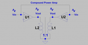
The schematic of the Compound Amp [CA] is attached. It can be readily assembled and its subjective performance assessed. Here are its broad-brush details:
1. U1 and U2 are high fidelity power amps I have. They are found in the working stereo receiver [Kenwood KR-6050] and the stereo power amp [Threshold S/150].
2. The 1:1 transformer is a power toroid made by Triad Magnetics.
3. By example, the input signal Vin [say 100 Hz] is offered to the Right and Left inputs of Threshold S/150. Its R and L power outputs [Vout] fed the power toroid as shown. Their Vouts are highly matched or equal in value as best I can measure their values with a digital voltmeter.
4. By a second example, the input signal Vin is offered to the R and L Aux inputs of the Kenwood receiver. Its tone controls were intially bypassed or set flat. Its power Vouts were adjusted with its volume control to the same values measured for S/150. The 2 Vouts from Kenwood were different in value driving the same power toroid. They were almost made equal by using its Balance Control which is stepped, and not smooth turning.
Some analysis;
1. With the power amps' signals equal in magnitude and of identical phase [depicted], neither one can dump power into the other. Thus the inter reflected impedance is large. May remind of the term common mode.
2. Suppose the stand alone left amp has a higher intrinsic THD than the right amp. Its harmonic signals [error] are wiped out by the right amp in the CA before they appear. This CA assembly does not allow the extra THD signals to be present on the right side of the traffo. May remind of a differential signal.
3. Both power amps drive power through the windings of the toroid. If one winding generates more common distortion than the other, this extra distortion is also wiped out before it emerges as explained in point 2 above.
4. It follows that CA is highly symmetric, and the toroid moves in the direction of ideality [~distortionless], as both amps clean it up , and take care of each other.
Attachments
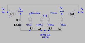
The complete schematic of the compound amp [CA] is attached and shows the following:
1. The 4 windings of the AC power toroid were interconnected as suggested by Triad Magnetics so as to give a 1:1 isolation transformer. Two additional options are available to interconnect the coils.
2. The loudspeaker loads the left power amp U1. It may be physically moved to load the right power amp instead of the left. This option is slightly different, and its effect probably irrelevant.
3. It follows that U1 does most of the work in the loudspeaker [R1 Load] , while the right amp is lightly loaded by the primary coils of the toroid [L1 and L3].
During operation using music input signals [Vin], I thought the following points explain the great sound of this CA.
1. The electrical conditions [voltage and phase] at the secondary [Vload], are essentially similar to the electrical conditions at Vout. Said otherwise, the electrical status [Vload] defaults to and/or closely tracks Vout. The objective and subjective performance on both sides of the toroid are similar. This result is sonically valuable.
2. Both amps see each other through the transformer. The right amp readily corrects any electrical imperfections it sees on the loudspeaker side.
3. [Vout] from the right amp is inherently very low distortion; because this amp is doing little work in the primary coils, and is doing some error correction work on the loudspeaker side.
4. The damping factor [DF] of the left amp is expected to be like that of the right amp which is inherently high due to the high value of its load. The DF of both amps can be argued to be ~equal and high; because Vload is ~ equal to Vout.
5. [CA] is electrically stable against oscillation.
More...
Attachments

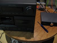
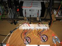
The attached pictures show an assembled stereo compound power amp. Each channel subscribes to the attached schematic on the right which is the same one I discussed in the previous post. Please note the detail for the far left picture:
1. The small/short block on the left of the view is a dual channel Class T [digital] amp made by Stellar Labs and was sourced from MCM Electronics. It is a hi-fi unit rated to give 15W/ch into 4+ Ohms load. Both of its power outputs drive the power toroid per the schematic/interconnection diagram. Only one of its amps which is connected to the toroid's secondary drives the Right channel loudspeaker.
2. The block on the right of the view is a dual channel Class AB analog power amp made by SONY, and is part of Mini HiFi Compact system. Its power outputs are rated to give 15 W/Ch [1% THD] when driving a 6+Ohms load. One of its power amps which is connected to the secondary of the power toroid, drives the Left channel loudspeaker.
The middle picture of this stereo compound amp system shows that each of the "monoblocks" has a volume control. The volume control of the digital amp was maxed, and the one on the SONY was adjusted during music play so as balance the acoustic outputs of the loudspeakers.
Surprisingly, it sounds great.
Attachments

The Threshold S150, and Kenwood KR-6050 I have are ~1983 productions [33 years old]. Their power supply capacitors are original. Both products work fine after each was idled for 72 hours so as to rejuvenate their caps.
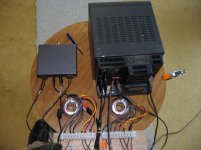
In the previous post, I showed the use of a 1:1 isolation toroid transformer. The resistance via Ohmmeter of its primary and secondary coils are 20 Ohms, and 23 Ohms respectively. The resultant current flowing through the coils at 60Hz is low noting that I measured 5-10 Vp-p [Vout] music voltage driving each loudspeaker. The S150 and KR-6050 performed quite well with this transformer; but they are high peformers to begin with as stand alone or without the transformer. So I used another power toroid which allowed each power amp in S150 and KR-6050 to dissipate more power in its primary and secondary coils.
The attached schematic on the left view shows how I did that using the indicated Triad transformer. One 115 Vac primary coil was paralleled with a 12 Vac secondary coil. The other 115 Vac primary coil was likewise paralleled with the other 12 Vac secondary. Here are the findings for the stereo system; with S150 and one toroid driving the Left loudspeaker, and KR-6050 and a second toroid driving the Right loudspeaker. The attached picture shows the assembly with S150.
1. The sound of this system is superb.
2. I give it a definite subjective step above the system using the first 115Vac:115Vac toroid.
3. The toroids warmed up slighly after prolonged music play.
4. I used a light bulb fuse [1 Ohm cold] in series with each power output of S150 and played music. Got a pulsating light show in both fuses for mostly bass information; maybe allowing ~0.3 A to pass through.
5. There's adequate power dissipated in the toroid by either amp so to impact favorably the other if needed.
Triad offers other 25 VA toroids which have two separate secondaries of 12 [in use; highest power use], 15, 18, 24, and 115Vac [lowest power use by amps]. The toroid VPT48-520 [two 24 Vac secondaries] maybe the best compromise in this application for power dissipation and favorable influence on subjective performace of one amp on its twin.
Attachments
Two high quality power amps of similar objective performance have a probability to sound different [subjectively] to a listener playing through the same loudspeaker. Many variables are at work in this A/B comparison. This differing subjective outcome suggests that the power output of music presented to the loudspeaker from Amp A is different from that of Amp B. I may even conclude that the power output from either power amp to the loudspeaker is different [in phase, harmonic content..]from that offered to a dummy load resistor which is the expected exact/accurate replica. Thus, this sound system is deficient.
This compound amp in the attached schematic suggests that the aforementioned deficiency [by the left amp/loudspeaker] can be remedied by using the right side power amp which is not directly connected to the loudspeaker. Both power amps are in constant signal communication via the power transformer which enables this timely correction. The resultant performance on the secondary side is the same as that on the primay side; because the right amp is continuously correcting any arising imperfection on the loudspeaker side.
This compound amp in the attached schematic suggests that the aforementioned deficiency [by the left amp/loudspeaker] can be remedied by using the right side power amp which is not directly connected to the loudspeaker. Both power amps are in constant signal communication via the power transformer which enables this timely correction. The resultant performance on the secondary side is the same as that on the primay side; because the right amp is continuously correcting any arising imperfection on the loudspeaker side.
Attachments

Compound Power Amp with Positive Current Feedback
Hello,
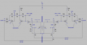
The compound power amp which I had described in the last posts has evolved. It now embodies Positive Current Feedback [PCF]. Please print its attached schematic and note the following explanations:
1. U1 and U2 are the two channels of a THRESHOLD S150 power amp. The two channels are twin performers.
2. The power outputs of U1 and U2 are mutually bootstrapped via the TRIAD power transformer. The two power amps can still talk to each other!
3. Each power amp drives an ADS L730 [3-way] loudspeaker [LS]. The two loudspeakers are considered to be twin performers.
4. Current flowing through each [LS] is sensed across a 0.3 Ohm power resistor so as to generate a voltage which is the source of PCF.
5. PCF from [LS] connected to the Right power amp is sent to the Left power amp. The other and independent PCF from [LS] connected to the Left power amp is sent to the Right power amp. The two independent PCF voltages are cross-coupled!
6. The $ sign vertical barrier shows that the two sides of the compound amp are mirror images and highly symmetrical.
7. The OPA2134PA invert phase and sum signals so as to present the proper overall phase of the input signals to U1 and U2.
8. The magnitude of each PCF is controlled by the value of the encircled resistors [5.6 K]. Values which are lower than [5.6 K] increase PCF and moves this system towards oscillation!.
This is a powerful [150 W] mono amp. The two loudspeakers are placed in the corners of the room. Both face me as I sit at the intersection of the floor diagonals listening to them. This specific amp [with PCF] and the corner placement of both [LS] is mainly meant to manage bass and standing sound waves.
It sounds great top to tight bottom at my listening position.
Best
Anton
Hello,
The compound power amp which I had described in the last posts has evolved. It now embodies Positive Current Feedback [PCF]. Please print its attached schematic and note the following explanations:
1. U1 and U2 are the two channels of a THRESHOLD S150 power amp. The two channels are twin performers.
2. The power outputs of U1 and U2 are mutually bootstrapped via the TRIAD power transformer. The two power amps can still talk to each other!
3. Each power amp drives an ADS L730 [3-way] loudspeaker [LS]. The two loudspeakers are considered to be twin performers.
4. Current flowing through each [LS] is sensed across a 0.3 Ohm power resistor so as to generate a voltage which is the source of PCF.
5. PCF from [LS] connected to the Right power amp is sent to the Left power amp. The other and independent PCF from [LS] connected to the Left power amp is sent to the Right power amp. The two independent PCF voltages are cross-coupled!
6. The $ sign vertical barrier shows that the two sides of the compound amp are mirror images and highly symmetrical.
7. The OPA2134PA invert phase and sum signals so as to present the proper overall phase of the input signals to U1 and U2.
8. The magnitude of each PCF is controlled by the value of the encircled resistors [5.6 K]. Values which are lower than [5.6 K] increase PCF and moves this system towards oscillation!.
This is a powerful [150 W] mono amp. The two loudspeakers are placed in the corners of the room. Both face me as I sit at the intersection of the floor diagonals listening to them. This specific amp [with PCF] and the corner placement of both [LS] is mainly meant to manage bass and standing sound waves.
It sounds great top to tight bottom at my listening position.
Best
Anton
Attachments
- Status
- This old topic is closed. If you want to reopen this topic, contact a moderator using the "Report Post" button.
- Home
- Amplifiers
- Pass Labs
- Compound Power Amplifiers