Biasing after Feedback resistor change
Well,
so I finally changed my feedback resistors to 470R in parallel to increase the gain to +/-27.6dB.
Now I noticed (but it might not be related - I did not check before) that I get different readings depending if I measure the P or the N channel boards.
Also measuring on different resistor groups (the parallel source resistors) on the SAME board gives me slightly different readings (around 5mV difference)
I did measure the voltage drop on each single resistor with a LM317 current source set at 0.78A, the procedure was pretty constitant to me, and grouped those with the same measured voltage drop for ALL the source resistors on both channels - I did NOT match the resistors with a bridge or similar.
I am confortable accepting a measurement difference, but now am doubting about where to measure to consider they are biased +/- equally.
....
Thanks for you help in advance!
Cheers,
Max
Hello, for the thermistors 4,7k what power must he choose and the precission please?
uchu007,
I am by far no expert but the types I found corresponding the BOM are 3% or 2% types, don't know if wattage is expressed on those.
I picked the first one on mouser, you can check if you find one you like better:
NTCLE100E3472HB0 Vishay / BC Components | Mouser France
Cheers,
Max
uchu007,
I am by far no expert but the types I found corresponding the BOM are 3% or 2% types, don't know if wattage is expressed on those.
I picked the first one on mouser, you can check if you find one you like better:
NTCLE100E3472HB0 Vishay / BC Components | Mouser France
Cheers,
Max
Do you have the nomenclature of the pieces? Because I just that of the store but its still vague on these pieces
Cordialy
Well,
so I finally changed my feedback resistors to 470R in parallel to increase the gain to +/-27.6dB.
Now I noticed (but it might not be related - I did not check before) that I get different readings depending if I measure the P or the N channel boards.
Also measuring on different resistor groups (the parallel source resistors) on the SAME board gives me slightly different readings (around 5mV difference)
I did measure the voltage drop on each single resistor with a LM317 current source set at 0.78A, the procedure was pretty constitant to me, and grouped those with the same measured voltage drop for ALL the source resistors on both channels - I did NOT match the resistors with a bridge or similar.
I am confortable accepting a measurement difference, but now am doubting about where to measure to consider they are biased +/- equally.
....
Thanks for you help in advance!
Cheers,
Max
Hi Max
I’m not quite sure I understand what you are measuring that is different on the N and P boards. When it comes to the bias voltages across the source resistors there is one variable that will increase the spread in readings and that is temperature differences between mosfets. If the mosfets are not mounted with consistent pressure you can get differences in the thermal conductivity to the heatsink, which will show up as differences in voltage across Rsource. This also goes for your initial measurements with the current source. If you do not wait for the temp to stabilize on each fet you will have more variation when installed in the amplifier.
If those differences are in the order of a few milivolts it is nothing to be concerned about.
Also, what about the differences between the N and P channel mosfets? There is no such thing as an 100% match.
Also, what about the differences between the N and P channel mosfets? There is no such thing as an 100% match.
You cannot expect a match in VGS between n and P channel mosfets. Have a look at the F5turbo manual written by Nelson Pass. I believe he goes into matching in that document.
Hi!
I've just finished building a pair of stereo F5s, using the v3.0 and PSU boards from the store and Modushop 4U enclosures - and all of the info available here obviously!
The amps biased OK with very little or no offset, and I've set P3 using an FFT to be the same on all 4 channels - so far so good!
The amps also sound fine, but do hum ever so slightly when the RCA cables from the preamp are connected. When the inputs aren't connected they're dead quiet! Any ideas what to do here?
Setup is: Source (CD, LP..) --> Sitronik Lucius Preamp / DSP --> Power Amps (2 F5s, 1 Thel AccuSound) --> Speakers (DIY Co-Axial horns + 15" bass; each channel has it's own amp, there's no passive crossover)
Cheers
Es
I used what Mr Pass had specified. The way I look at it Pass amps are pretty much the top tier for sound quality and if Mr Pass recommends parts then they will sound fine. We are all free to experiment, of course, but I just don’t have the time or funds to experiment with resistor types and simply use what is recommended by the designer.
Hi,Please pose some in-focus, well-lit photos, particularly of the wiring.")
was away for work, but here goes!
BTW., I just realized that I posted in the Turbo thread, but have actually built regular F5s.... should I move the posting or re-post elsewhere?
Here's a pic of amp #1:
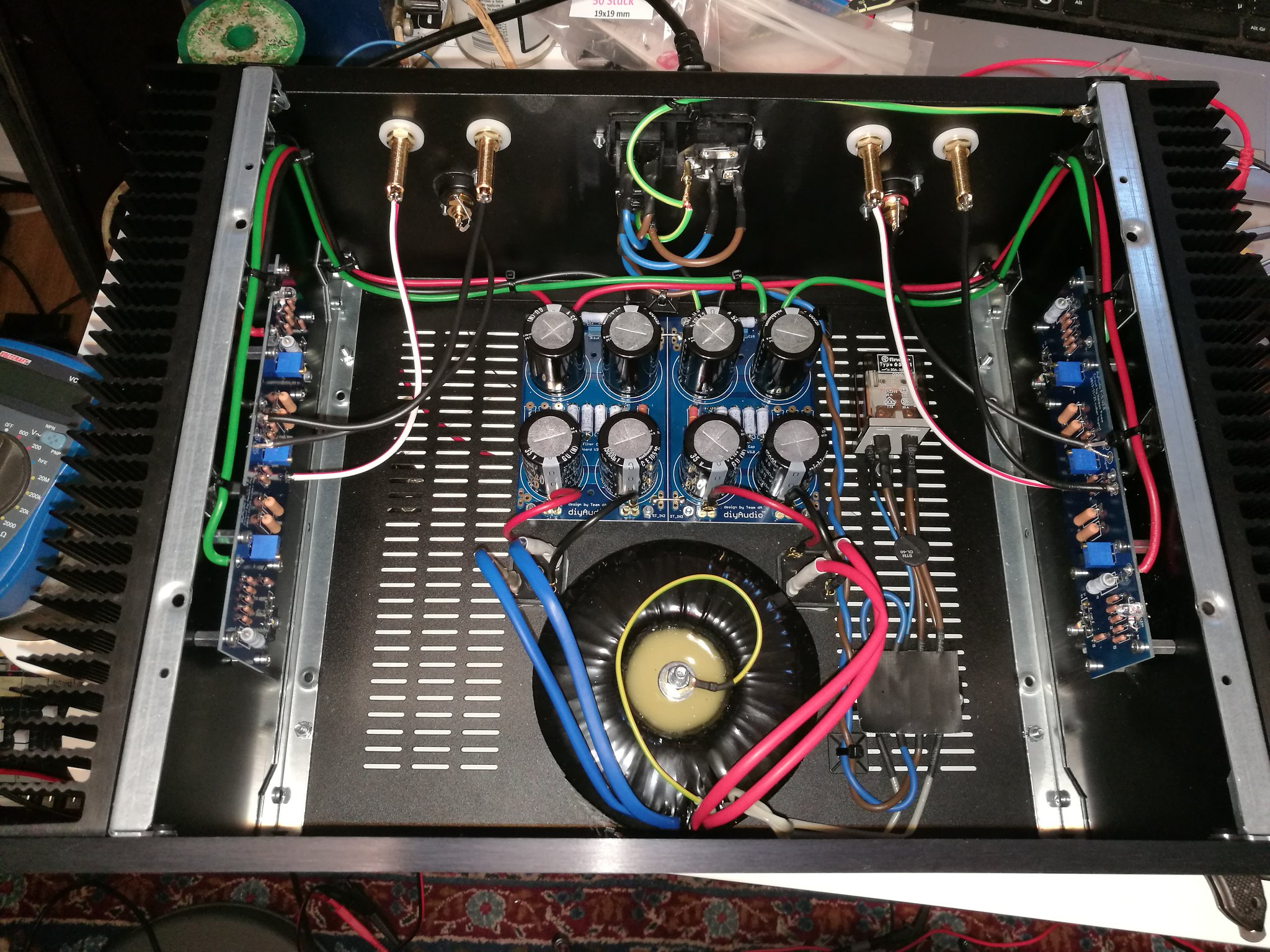
On Amp #2 I tried attaching the speaker negative wires directly to the PSU ground. The function ground is de-coupled from chassis ground with a CL-60 thermistor.
Should I try making a true star-ground, where all the negatives "feed off" from?
Cheers
Es
...not anything to do with resistor brand.
Maybe i should have quoted
...I used MPC74 last time, and need more. I'm not keen on their construction... ...Any suggestions?
It's a screen - at least I think so...The earth wire on the transformer bolt - have you created a 'shorted turn' or is that an electrostatic screen?
Cheers
Es
- Home
- Amplifiers
- Pass Labs
- F5 Turbo Builders Thread