
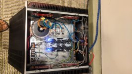
Each output board get it's own connection to the power supply, each output board gets connected to the speaker terminals doubling the number of conductors for less resistance, perhaps more capacitance and inductance, who knows. I have not bench tested the amps, they are super stable, DC offset around 10 mv when thermal stability is reached. I hope this helps a few diy'ers. Cheers!
Here is what I can share: I finished the V3's last week. In 2017 I had built a V2 with 4 cascoded Jfets per front board running at +/- 43 volts, bias at 0.7 A per output devices, total bias 2.8 per channel, using the store's power supply boards it sounded fine but I wanted more power my NHT 3.3's.
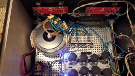
This time a used Toshiba Jfets bought on eBay from a seller Nelson recommend the seller based on Sacramento CA (punkydawgs is his seller name), I upgraded the power supplies using Tea-bags dual rails boards running the same voltage. I took a chance buying Panasonic 27,000 uF 50 V capacitors from a guy on eBay (I think he has more of them, $8.99 a pair) they are doing fine so far, no humming on the outputs.
What I have realized is: Toshiba's Jfets are quieter, sound better (I gonna get in trouble by saying this but my ears tell me it's true) they are very low noise= more subtle sounds come through. More class A = sweeter sounds at loud volumes, currently running at .350 V across Rs's so total bias is 5.6 A per monoblocks. I think I'm getting close to 100 watts class A. The upgrades have made a big difference in the sound.
.350V or 0.7A pr device will give you a total bias of 2.8A on a 4 outputpair amp. not 5.6A.
.350V or 0.7A pr device will give you a total bias of 2.8A on a 4 outputpair amp. not 5.6A.
Quiescent point 8 transistors conducting 0.7A. 5.6 A going from V+ to V-. That is what I understood from reading Master's F5 manual. If you only count one side of the push-pull configuration then the F5 has 1.3 A of bias and yes a F5T V3 will have 2.8 A bias.
that means 4 vertical pairs
conditionally , 4 current verticales
each vertical showing 350mV across 0R47 source resistor , so roughly 700mA
700mA multiplied with 4 = 2A8 Iq per channel
conditionally , 4 current verticales
each vertical showing 350mV across 0R47 source resistor , so roughly 700mA
700mA multiplied with 4 = 2A8 Iq per channel
Thanks, that is very clear. Thank you. So the class A envelope of this amplifier will be around 47 Watts into 6 ohms?
you will have about 95W class A at 6ohm.
peak class A current is 2 times bias. so: 5.6A peak. and 3.95A rms
3.95Ax3.95Ax6ohm=93.6W class A at 6ohm
peak class A current is 2 times bias. so: 5.6A peak. and 3.95A rms
3.95Ax3.95Ax6ohm=93.6W class A at 6ohm
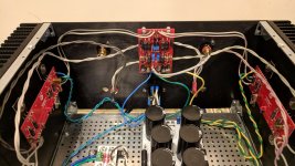
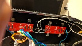
2 more. It's a bit messy but works fine
Thanks for the photos.
By my calculations, if you wire it that way, it is unnecessary to use anything over 20 AWG.
For silver coated Belden 20 AWG, the Max Amps that may be carried is 6.5 Amps. As the boards are in parallel, the total amps that can be delivered to the speaker by the wiring is 13.
Finally, since P = I * V = I * I * R the max power supported by the wiring is:
169 watts into 1 ohms.
-
338 watts into 2 ohms.
-
776 watts into 4 ohms.
-
1552 watts into 8 ohms.
Using 20 AWG and wiring the output boards in parallel does not pose an issue.
If the boards are wired in series, then the limit of 6.5 A is at the power supply side and the output side.
Now, the max power supported by the wiring is:
42.5 watts into 1 ohms.
-
85 watts into 2 ohms.
-
170 watts into 4 ohms.
-
340 watts into 8 ohms.
Note this assumes you have a wire run from each output board to the speaker posts -- or double up from the F5T input board.
This may be a stupid question, but what determines the max power output after the amp exhausts the class A bias and transitions to class B operation? How is that calculated?
For example, I measure 320 mV across my source resistors, which means I'm running about .64 amps of bias current per output channel. This gives me about 104 W peak class A into 8 ohms and 73 W RMS. Will the amplifier just clip past this point, or will it transition to class B? If it transitions, how can I calculate how many extra watts are on tap?
For example, I measure 320 mV across my source resistors, which means I'm running about .64 amps of bias current per output channel. This gives me about 104 W peak class A into 8 ohms and 73 W RMS. Will the amplifier just clip past this point, or will it transition to class B? If it transitions, how can I calculate how many extra watts are on tap?
care to describe that little more - rails , how many output pairs (each vertical pair having 320mV across 0R47)?

standar V2 = 2 outputpairs. 0.64A pr device = 1.28A bias. that is about 25W class A at 8ohm.
peak class A pover is 2 times bias. so 2.56A peak.
2.56/1.414=1.81Arms.
1.81x1.81x8=26.2W class A at 8ohm.
32V rails minus about 3V loss in the curcuit is 29V
29/1.414=20.5Vrms
20.5x20.5/8=52.3Wrms class A/B at 8ohm.
peak class A pover is 2 times bias. so 2.56A peak.
2.56/1.414=1.81Arms.
1.81x1.81x8=26.2W class A at 8ohm.
32V rails minus about 3V loss in the curcuit is 29V
29/1.414=20.5Vrms
20.5x20.5/8=52.3Wrms class A/B at 8ohm.
standar V2 = 2 outputpairs. 0.64A pr device = 1.28A bias. that is about 25W class A at 8ohm.
peak class A pover is 2 times bias. so 2.56A peak.
2.56/1.414=1.81Arms.
1.81x1.81x8=26.2W class A at 8ohm.
32V rails minus about 3V loss in the curcuit is 29V
29/1.414=20.5Vrms
20.5x20.5/8=52.3Wrms class A/B at 8ohm.
Thanks - this makes sense to me.
Exactly.
Of note is that class A/B simply means that the amplifier works in class A for part of the time. Remember the explanation of when the F5 leaves class A in the F5 manual? Look at the current flow this way:
At idle both N channel and P channel MOSfets are conducting the same amount of current.
When a speaker is attached and there is no signal ( the amp is idle ) the current *still* flows only through the transistors, and not through the load. Why?
Because the load is at 0 potential. It is less inviting for current to flow between the rails and zero than between the positive and negative rails. And biasing has balanced the amount of current that flows through each MOSfet at idle.
When a signal is applied, the current flow is unbalanced. Let's say the P Mosfet begins to close and the N MOSfet opens more.... there is more current flowing through the N MOSfet, and Less through the P.
The current that was once flowing through the P channel MOSfet needs to go somewhere.... it goes through the load. So you can think of the signal "steering" the current away from one MOSfet and through the load instead.
As the P channel restricts X amps, the N channel allows X amps. So, as half of the flow of the bias current in the P channel is subtracted, half is added to the N channel. When the P channel has blocked all current, the N channel has had it's current doubled.
At this point, the amplifier is operating in class B.... one transistor is conducting ALL of the current, and ALL of it is going through the load... the other transistor is pinched off.
As the signal polarity inverts, both MOSfets begin to conduct again, back into Class A operation, and the cycle repeats with roles reversed.
So Peak Class A current is twice the current flowing between the rails at idle-- which is twice the bias current.
Class B Peak is limited by the rail voltages.
=======
- Home
- Amplifiers
- Pass Labs
- F5 Turbo Builders Thread