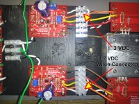
Here is another strange one. The D+ readings are stable with all leads connected except for the orange wire on the bottom channel - also the one that's been troubling. As soon as that orange wire is connected that voltage jumps to ~ 11.2 - 12.3 VDC. Remove it and the voltage returns to 3.0 Volts when read from the bias board side of the screw terminal. Though the trimmer on that board works to get to 3 volts, I haven't left the power on long enough to try to bring down that higher voltage. My concern is burning something else out whether or not I can get proper adjustment with the trimmer. The fans on the heat sink are active (same switch) so there is a cooling factor.
Attachments
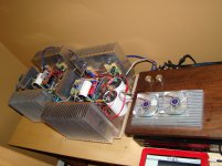
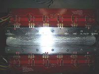
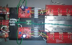
Here they are..my bastard ba3 mono blocks. buz901/906 outputs with ba3 front end and bias. For the time being all the outputs run parallel but they could be easily configured as balanced amps...that's a hint buz...
Rails are at +/- 20 volts bias set at .9 amp per output device.
Dead silent with no input.
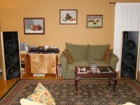
Ok back to the couch to enjoy my work.
Evan
Rails are at +/- 20 volts bias set at .9 amp per output device.
Dead silent with no input.
Ok back to the couch to enjoy my work.
Evan
Attachments
Bob, I didn't try any other caps for this exact build. The audyn cap sounds good enough for me.
Hopefully you will get your set working soon so you can sit back and enjoy it. If you want/need them I have a pair of Complementary Output boards and 9.1 volt zeners. I also have a bunch of irfp240/9240 that could be matched for the outputs.
Hopefully you will get your set working soon so you can sit back and enjoy it. If you want/need them I have a pair of Complementary Output boards and 9.1 volt zeners. I also have a bunch of irfp240/9240 that could be matched for the outputs.
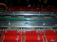
Thanks Evan, but it appears the silpads are the problem. Since I had the parts on hand, I just built another output module. Everything checked out (3 volts where needed) on the initial power-up. After ~ 8 minutes the voltage jumped back up, I checked for continuity from all the fet pins and found many that beeped at me.  They all were clear before I did the final tightening of the screws on the clamping bar. In addition, I found three bad points on the output board that has been working.
I have to admit I haven't been using "clean room" practices over the past few days, and the extra tightening may have forced some metal bits through the pads. I'm using TO-220 mica pads that have a 0.52 in. width that just covers the back plate on the transistors. There may have been some movement while mounting and tightening. Mouser has some pads at 0.54 in. that might give better coverage.
I'll look around locally for some fresh pads, but RS appears to have moved all their insulators to online only. The Keratherm pads from the store look great, but aren't available yet, and this build would require about a $40 investment with four output boards - OUCH!
In any event, I'll try to clean/re-work what I have later this afternoon but I haven't had much luck avoiding sheering of the mica after the first use.
They all were clear before I did the final tightening of the screws on the clamping bar. In addition, I found three bad points on the output board that has been working.I have to admit I haven't been using "clean room" practices over the past few days, and the extra tightening may have forced some metal bits through the pads. I'm using TO-220 mica pads that have a 0.52 in. width that just covers the back plate on the transistors. There may have been some movement while mounting and tightening. Mouser has some pads at 0.54 in. that might give better coverage.
I'll look around locally for some fresh pads, but RS appears to have moved all their insulators to online only. The Keratherm pads from the store look great, but aren't available yet, and this build would require about a $40 investment with four output boards - OUCH!
In any event, I'll try to clean/re-work what I have later this afternoon but I haven't had much luck avoiding sheering of the mica after the first use.
Attachments
Last edited:
Invalid Request
These are an excellent alternative to the Kerofal. The only other thing I would be carfeul of is that you evenly tighten your bolts on the aluminum bars. You do not want to create uneven pressure on the fets.
These are an excellent alternative to the Kerofal. The only other thing I would be carfeul of is that you evenly tighten your bolts on the aluminum bars. You do not want to create uneven pressure on the fets.
will this work ....
Hi,
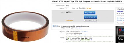
Would this work for insulators,
I have a roll on it's way,but was using it in my transformer builds,
NS
Those look to be the best I've seen - with a good margin. I'll order some. Thanks.
Hi,
Would this work for insulators,
I have a roll on it's way,but was using it in my transformer builds,
NS
Attachments
Hi andrewT
I have to look ,but that stuff is cheap,5 to 10 a roll of 100 ft,
and you need to use heatsink grease to coat them on both sides?(You need to coat both sides to exclude air from the interfaces.)
I did email the supplier,my roll is in Cal maybe they will have it here soon and I'll mic it and see how thick it is.
I do them anyway helps keep them in place,lol.
Thanks,
NS
yes.
You need to coat both sides to exclude air from the interfaces.
I hope you ordered 1mil thickness and not 6mil.
I have to look ,but that stuff is cheap,5 to 10 a roll of 100 ft,
and you need to use heatsink grease to coat them on both sides?(You need to coat both sides to exclude air from the interfaces.)
I did email the supplier,my roll is in Cal maybe they will have it here soon and I'll mic it and see how thick it is.
I do them anyway helps keep them in place,lol.
Thanks,
NS
Last edited:
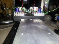
!!! MICA REALLY SUCKS !!!
But you guys probably already knew that and were sitting back chuckling while I went through my baptism of fire.
I had everything perfect three times - once with all new pads - and as soon as I tightened up just a little the insulation went away. I went so far as to pohish the heatsinks with 1500 grit on a marble plate and still had failures. Never again.
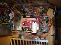
So in desperation I robbed the ceramics from the Honey Badger knock-off. They aren't as efficient but those pesky continuity beeps are a thing of the past. There is still some tweaking to be done as the DC offset on the top is 1.8 volts and the bottom reads 3.2. Reading the center pins of the output transistors, the bottom is running about 10 - 12 degrees hotter. That's the one with the 12 volt zener.
But I ain't touching nothing till someone tells me to - except maybe turning the power on a couple dozen times to get that dual 3 V reading in a sense of total victory.
But you guys probably already knew that and were sitting back chuckling while I went through my baptism of fire.
I had everything perfect three times - once with all new pads - and as soon as I tightened up just a little the insulation went away. I went so far as to pohish the heatsinks with 1500 grit on a marble plate and still had failures. Never again.
So in desperation I robbed the ceramics from the Honey Badger knock-off. They aren't as efficient but those pesky continuity beeps are a thing of the past. There is still some tweaking to be done as the DC offset on the top is 1.8 volts and the bottom reads 3.2. Reading the center pins of the output transistors, the bottom is running about 10 - 12 degrees hotter. That's the one with the 12 volt zener.
But I ain't touching nothing till someone tells me to
- except maybe turning the power on a couple dozen times to get that dual 3 V reading in a sense of total victory. Attachments
Last edited:
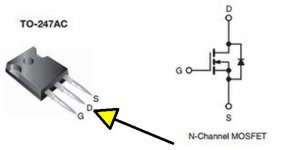
When you say top and bottom, do you mean top and bottom output boards? You can chek each fet for isolation by simply measuring the drain pin and the sink with the probes. If all is fine there, it is time to power it up. If you have burned out fets in the output from the last attempt, you will have problems. If your fets are not matched for a given current at a given Vgs, you will have problems, as they will not share the current equally. if all is OK, then adjustment is just a matter of time and patience. THe 12V zener is irrelevent. It provides 12V to the pot, which forms a voltage divider, splitting this voltage.
- Home
- Amplifiers
- Pass Labs
- Burning Amp BA-3