new file at passlabs.com/np
hehe
type it
sorry if Papa already announce it
now you all can see how big Teaser he is...........
now -in line,and ........to Meka............. 😉
hehe
type it
sorry if Papa already announce it
now you all can see how big Teaser he is...........
now -in line,and ........to Meka............. 😉
Nice project for those who wanted Pass gear for their home theater.
( and have big transformers lying around 😀)
Regards,
Vix
( and have big transformers lying around 😀)
Regards,
Vix
Well, it doesn't do ya much good without UGS 1, 2, and 3 now, does it?
Funny, I've been trying to find one for sale used. --there's no way I'd ever have the time to build one.
Funny, I've been trying to find one for sale used. --there's no way I'd ever have the time to build one.
I believe there's a thread here about UGSs. The schematics in it may or may not be exactly what Nelson is using, but they will work.
Grey
Grey
If I'm not completely mistaken, these are the UGS-threads:
http://www.diyaudio.com/forums/showthread.php?s=&threadid=86300
http://www.diyaudio.com/forums/showthread.php?s=&threadid=73931
Cheers, Hannes
http://www.diyaudio.com/forums/showthread.php?s=&threadid=86300
http://www.diyaudio.com/forums/showthread.php?s=&threadid=73931
Cheers, Hannes
and here for the original ACAUDIO-UGS:
http://www.diyaudio.com/forums/showthread.php?s=&threadid=54826
http://www.diyaudio.com/forums/showthread.php?s=&threadid=54826
Great 😎
Our great Philbyx is experimenting a version 😉 Follow links from here : http://www.diyaudio.com/forums/showthread.php?postid=1167632#post1167632
The schematic is a bit outdated, and a "Vbe multiplier" (a BJT based one, since the used output mosfets begin to conduct before a Mosfet bias control becomes active 😉 )
The first channel has been tested de auditu (wow,great, etc...😀) and the second channel in on the bench for testing. I think there'll be more to come quite soon.
Attachments
Something puzzling me...
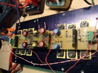
A grand total of 40 Mosfets (8/channel). Bias per mosfet : 1A (470mV accross 0R47 source resistors) Supply at 32V.
So each mosfet idles at around 30W, leading to a total dissipation of 1.2kW at idle 😕
Where did I go wrong ?
A grand total of 40 Mosfets (8/channel). Bias per mosfet : 1A (470mV accross 0R47 source resistors) Supply at 32V.
So each mosfet idles at around 30W, leading to a total dissipation of 1.2kW at idle 😕
Where did I go wrong ?
CheffDeGaar said:
Where did I go wrong ?
Nelson appears to be pulling the old switcheroo, going back to the older Aleph push-pull output stage. The top devices are Ns, biased pretty decently. The bottom is a little more complicated. There are P-ch devices, biased lightly, running in parallel with a current source, biased heavily. What modifications he might have made to the older output stage, I do not know.
Grey
GRollins said:The top devices are Ns, biased pretty decently. The bottom is a little more complicated. There are P-ch devices, biased lightly, running in parallel with a current source, biased heavily. What modifications he might have made to the older output stage, I do not know.
Grey
Grey, even if only the upper fets were heavily biased, it "only" would halve the dissipation, leading to 600W at idle, or 300W per heatsink. To reach 25° above ambient, this assumes a Rth of 0.08°K/W... Pretty cool 😀
But I really doubt P and N fets are biased differently, and I do not see any arrangement looking like the Aleph 0 topology...
I need enlightenment 🙂

Nelson Pass said:The N's are biased somewhat higher than the P's.
You mean like the Neck and the Pheet ?
(suspicious little me is wandering off to UGS5 again)
Hi Nelson,
Thank you very much for posting the X5 service manual. It is very much appreciated. This is a really big deal. It is the first time that service/schematic manual/info for a SuSy based power amp has been disclosed.
There is a wealth of information in this handful of pages.
After two pages of posts I just figured it was time someone said thank you.
Thank you again.
Graeme
Thanks Nelson 😎. And thanks for putting the document online 😉 And apologies to Grey for my boldness (not sure of the english term, but it may sum up to "me little grasshopper") 🙂Nelson Pass said:The N's are biased somewhat higher than the P's.
So I do not have to trust the schematics saying "0.47V bias" in front of the source resistors, both for the P one and the N ones... I'm confused, to say the least.
And after a careful reading of the "adjustment" paragraph, I still can't figure out what happens here. The bias is to be adjusted by monitoring the voltage on a source resistor. But the N ones, or the P ones ?
I surely miss a point here...
Interesting reading, but I don't know what you are talking about
as I can't open Papa's webs at all.
Choky, could you send me one copy? Many thanks.

as I can't open Papa's webs at all.
Choky, could you send me one copy? Many thanks.
Babowana said:....
Choky, could you send me one copy? Many thanks.
why should I?
gimme one good reason...........
(CID-CMB)
- Status
- Not open for further replies.
- Home
- Amplifiers
- Pass Labs
- to all greedy boyz