Hi
Can't get my headphones replaced in warranty during COVID lockdown so I am forced to fix the old ones.
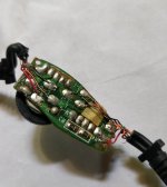
I have a pair of old headsets that have this volume potentiometer that I would like to bypass entirely. And keep the volume full at all times.
Could anyone tell me which pins would I need to manipulate?
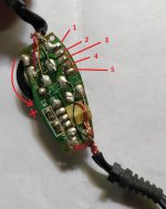
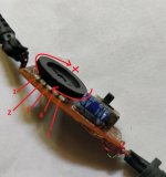
I have numbers the pins and shown which direction the potentiometer goes for volume increase.
Thank you
Can't get my headphones replaced in warranty during COVID lockdown so I am forced to fix the old ones.
I have a pair of old headsets that have this volume potentiometer that I would like to bypass entirely. And keep the volume full at all times.
Could anyone tell me which pins would I need to manipulate?
I have numbers the pins and shown which direction the potentiometer goes for volume increase.
Thank you
Attachments
Yeah.. I thought of that. But that would require more soldering than I think I am capable of. And I am not sure the wires will actually meet each other's lengths. Those rubber block things keep them at a length from each other inside the plastic enclosure that houses this entire PCB
Is there really no way to just join 2 or more points with another wire to get the same effect?
Is there really no way to just join 2 or more points with another wire to get the same effect?
Is there really no way to just join 2 or more points with another wire to get the same effect?
If you cut the pot pins on the top of the pcb and remove it, then you can safely use two short jumpers
(or low value resistors) to connect red to red, and black to black.
I disconnected the green wire which goes the R-I (guessing it's Right in) and connected to the green wire (pulled from R-O - may be right out)
Did the same with L-I and L-O... the light red wire. (the dark red is mic. I think)
Would this cause any problem in the future? Or something damage to the onboard DAC/amp in my laptop?
Note : I don't use the mic on this headset
What is the wire connected to the pin 1 of the potentiometer?
Did the same with L-I and L-O... the light red wire. (the dark red is mic. I think)
Would this cause any problem in the future? Or something damage to the onboard DAC/amp in my laptop?
Note : I don't use the mic on this headset
What is the wire connected to the pin 1 of the potentiometer?
Last edited:
- Status
- This old topic is closed. If you want to reopen this topic, contact a moderator using the "Report Post" button.