Trust me on this please, you will be fine. The Fs will come down after a while, it is mostly the 'spider' part of the suspension that needs a good workout.
..but look at the differences in sensitivity.

Joe:
Interesting -- I'd be less inclined to use a crossover pcb if there was adequate room to spread the big coils out, but your pcb could be very beneficial in a more compact environment, such as the Hamlet.
That said, I'm a little surprised that a crossover pcb suitable for the Elsinore would also be appropriate for the Hamlet. You are a wizard.
Regards,
Scott
Attachments
..but look at the differences in sensitivity.
It shouldn't change *sensitivity, in fact, it does not. Yes, the Fs changes because of the suspension variabilities, but the mass of the cone/moving parts does not change and neither does the BL factor/force.
I wish I had a copy to hand of that study done back in the eighties where batches of the same driver were installed into the same box and measured. Yes, there were batch differences, but when driver Fs had gone high the Vas had become less and vice versa. Measurements in the box varied little, the alignment barely changed. This is good news because it means that we have a self-correcting mechanism within the driver design. It is not perfect, but then anything is rarely that.
If I had that article/study, I would have posted it. But I never forgot the gist of it.
*EDIT: Unless I somehow mistook the point you were making?
Last edited:
Lightning Phil,
Usually it's better to follow the original specs for a well thought out design.
Not sure the effects of increasing the length internally will end up having on the cabinet; although the Elsinores are designed as a bass-reflex, it is likely that there is some 1/4 wave resonance at play too. Your elongated the length probably changes something, but you might be ok.
Good luck with rest of the build.
I almost always use things out of spec - I'm a pulsed power engineer and semiconductors are not meant to be abused the way we treat them. It's good fun running things close to the limit of releasing the magic smoke within.
For the Elsinore project, I steered as close to it as possible, with the exception of the height increase. The effect of which was probably lost in the tuning phase with the wadding. They now sound awesome. Hat tipped to Joe! Would love to hear some completely stock ones.
I'm going to be belligerent and happy with the height increase as it's done now
And I am enjoying having the tweeters at ear level when seated. Something I found frustrating with some KEF (both Q series and reference range), which were shorter and projected the sound from a lower angle. It's a personal thing.Perhaps another way to look at it, is that altering the height a bit, still can result in a wonderful speaker, so they're potentially not hair trigger sensitive to this. But this opinion is formed from a single data point with no reference to the originals.
Will post a pic in a bit of the seriously sketchy small signal crossover that's being used.
Lightning Phil,
Glad to know that the speakers are sounding good.
Having the tweeters at ear level make sense. Joe had also advised the same a year or two back, but with putting a 4 inch (10 cm) platform below the speaker. You did it your way, and it turned out fine, so now sit back and enjoy the music!
Glad to know that the speakers are sounding good.
Having the tweeters at ear level make sense. Joe had also advised the same a year or two back, but with putting a 4 inch (10 cm) platform below the speaker. You did it your way, and it turned out fine, so now sit back and enjoy the music!
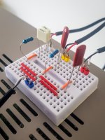
Pic of sketchy crossover attached.
It's there's one for each speaker running into separate Denon POA-F100 amps, which each have 3 channels. This allows the tweeters, top 2 drivers and lower 2 drivers to be on separate channels and thus alter the frequency response before amplification rather than after.
The amps were eBay finds and turned out to have slightly dead input op-amps. The origination (NJM074) chips seemed hard to get unless I want 50 or to trust eBay again, so went with what seemed an upgrade (TLE2074). They work so it'll do.
Have attached the schematic as analyzed in SiMetrix. It shows an experiment in rolling off the lower drivers earlier. Since then, the capacitance has been reduced to raise the cutoff. The stock response reverberates the room a little with the current speaker placement, hence the tinkering.
The input to all the mid range drivers has been reduced as I've wired them in parallel rather than series for a 4 ohm load for the amp stages (can't do this the the tweeter, so it remains ~8 there).
I do long for the day when I can build my dream valve amp and make the crossover as it should be. But this'll do for now. No measurements taken as yet (I do have kit), but have a good enough ear to iron out glaring things. Sufficiently pleasing to have lost a good number of hours sitting in front of them.
Attachments
Lightning Phil,
Glad to know that the speakers are sounding good.
Having the tweeters at ear level make sense. Joe had also advised the same a year or two back, but with putting a 4 inch (10 cm) platform below the speaker. You did it your way, and it turned out fine, so now sit back and enjoy the music!
Thought about blocks, or even having the base of the enclosure solid and therefore leaving the internal space identically shaped despite a taller exterior. But had to make a decision and went with the way it is. Decisions are hard


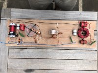
The 18mH inductors usually have low DC resistance and hence larger than they need to be. I have ordered a batch of them with around 3.2 Ohm resistance (DCR) and they are about 40% the size and weight of the Jantzen I have been using which were 0.83 Ohm. What you do is reduce the series resistor value and you still end up with the correct value. The ones I have ordered are also Jantzen and decent quality. There is no need to spend money when it adds no value.
For the Elsinore project, I steered as close to it as possible, with the exception of the height increase. The effect of which was probably lost in the tuning phase with the wadding. They now sound awesome. Hat tipped to Joe! Would love to hear some completely stock ones.
Great! Maybe some pics of your Masterpiece?
MAY 25, 2021 HAMLET UPDATE:
Both the computer modeling is nearly done and looking good as well as the PCB for the Crossover.
As mentioned earlier, see the below attachment, the PCB will be the same for both Crossovers, Elsinore and Hamlet.
The main difference is that "L1" is not used for Hamlet Mk6 which has 13 components where Elsinore Mk6 has 14.
IIt means the Hamlet Crossover will use the same parts designations as the Elsinore Mk6, the only difference will be the values, but even here some are the same, such as "C1" is 1.8uF for both, so is "L4" as 18mH and so on.
The Crossover is shown below. It may yet get a few tweaks before being ordered this week, but that is what it will look like.
I am also getting some 18mH "L14" inductors that have higher DC resistance and hence not so big and massive and more reasonable price. I am getting 30 of those, but I believe another 30 will also available from speakerbug.com.au for those in Australia.
The parts list will show all the Jantzen parts list numbers, like all the inductors, and info on sourcing, etc.
So we really are getting things very organiised and yet have some flexibility.
Attachments
I know it's been a rough year, Joe, but you've lost one less month than you think.
It's just April, or I've missed our anniversary and our birthday(and she'll put me in a home if I forget her birthday, since it's mine as well).
But a pair of Hamlets might be a nice present....
It's just April, or I've missed our anniversary and our birthday(and she'll put me in a home if I forget her birthday, since it's mine as well).
But a pair of Hamlets might be a nice present....
Last edited:
Very pleased with the modeling.
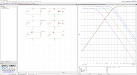
Below is the graphic with just a Green colour. This is 15 degrees Off Axis and hence 100-20 degree Off Axis is the ideal listening position, with the idea that angling in and out to control the brightness tonally. So toeing in increases brightness and toeing out the opposite.
This is demonstrated by the second graphic plot, where Red in On Axis (not recommended for listening), Green for 15 degrees Off Axis (recommended for listening)) and final Blue is 30 degrees Off Axis. This Blue plot approximates the Power Response and what I see here is very pleasing with a slope that looks just right.
Next is getting parts together and do the Crossover and then see how well the modeling has worked. Some final tweaking of the Crossover may need to be done, but in some cases in the past, if the modeling is spot on, there will be no further changes. But we shall see.
EDIT: Final graphic added, impedance and electrical phase angle. Flat impedance just under 4 Ohm and a very easy load for nearly every amplifier.
Attachments
Last edited:
I know it's been a rough year, Joe, but you've lost one less month than you think.
It's just April, or I've missed our anniversary and our birthday(and she'll put me in a home if I forget her birthday, since it's mine as well).
But a pair of Hamlets might be a nice present....
He's on Australian time. Where we spring forward an hour, they spring forward a month!...
This measurement would seem to ignore the effects of lobing and if so may not be a good approximation for power.Blue is 30 degrees Off Axis. This Blue plot approximates the Power Response
This measurement would seem to ignore the effects of lobing and if so may not be a good approximation for power.
I am old school and making a generic statement quoting Vance Dickason, that a quick approximation of the power response, look at the response 30 degrees off-axis. It is merely an indicator and also based on my experience. I meant no more than that. Lobing is not ignored, don't forget this is simply an update going from the HDS Nomex driver to the new SB17MFC35-8 driver and that the tweeter is the same, so I am not reinventing the wheel here. I have that crossover built already and now ready to make the changes to it, and all is in hand.
No, it's the measurement that I was saying that has in this case ignored lobing.
By the way, lobing is dependent on the crossover so if you change one....
Oh yes, it is indeed.
But that is why I mentioned that this is an adjustment of the design that was previously done and the same tweeter/waveguide combination. At the end of the design cycle, the final result will be checked via 1/6th Octave RTA measurements in-room.
But I assure you, it will check out OK. Note that the graphs I posted a few msgs back are not real measurements, they are the results of modeling after exhaustive pseudo-anechoic (time edited windowing editing out reflections and done outside) at 2M.
As you understand the technical aspects, the dB-SPL referenced to 1M/2..83V, but in reality 5.65V stimulus to compensate for 2M and hence nominally 4W instead of 1W.
These farfield measurements were coupled with nearfield measurements of the MidBass driver (less than 10cm) and rear port (1ocm) that are summed and merged into a single response and done 0 degrees, 15 degrees of-axis and finally 30 degrees of-axis.
So three models are made and changing the crossover to one, you need to change the other two, and so on. Because they share the same Z plots, when any changes to one crossover is made, then changing the other two, only the acoustic responses should change and you can use the system Z plot to make sure that it has not changed. That prevents potential error. It is a beautiful thing when it all comes together.
If you ever come up to Sydney, I can show you, but the above is but the tip of it. But if you get the data right, the raw measurements, then the preparations of multiple files that can be shown to have checked multiple reliability tests, then sitting down and constructing the crossover in SoundEasy (a program that originated in Melbourne by Bogdan Raczynski of Bodzio Soft [you may know, but some readers here may not]) which is used by speaker designers all over the world. If the data is good, then the best is when you do this part.
I have also gone over the previous Mk2 results (there are no model numbers between Mk2 and Mk6) and compared the results and some values are changed, out of 13 components, it looks like 9 needs to be changed, not drastically in values, so the design aims and how things hang together from the earlier on is maintained.
Instead of changing the existing crossover, I think I will wait for the PCB design. So I will likely place the order today. I also need to order crossover parts and that might take a bit of time too. Then the in-room RTA measurements and because I know this room well (for twenty-one years) I will have no problem in recognising by measurements, and hearing too, that it all went well and if any further tweaking is required, but in this case the measurement comes first. I know what it needs to look like. Yes, I am a measurement guy!
So the guys need to be just a little more patient, but we are definitely getting there.
A month would be good and earlier even better.
Last edited:
- Home
- Loudspeakers
- Multi-Way
- The "Elsinore Project" Thread