The above example was printed on a Bambu Lab printer. Note the main issues are the flat area at the front, and also, can you see that white line near the top and left side near the mounting hole, that is a so-called "seam" - it looks even worse than the picture if seen in direct light. In low light like in my room, you don't notice anything until you look up close and then it is not acceptable. The other attempts were done at Monash University and slowed up for max quality (50+ hours) and they have available quality machines that I don't have, and yet the result still not that great.
The bottom line is that we have the design side of things right, this seems to be an entirely a cosmetic issue. The above example in the photo, that took near 4 hours to do, each.
Joe, just thinking aloud - these are imperfections that some epoxy filler and sanding can reduce?
Please note that different materials and printers wilk produce different results. I used MJF to get WGs printed for another project, and they came out very nice.
With PLA or ABS you might get coarser results with more banding and visible seams.
If your dinensions are final and good to go, you can order MJF 3D printed items online.
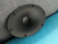
Here you go with a pic of the MJF printed WG I mentioned earlier. If you are interested, I can share details of the site where I placed the order and guide you through the options.
Please note that different materials and printers wilk produce different results. I used MJF to get WGs printed for another project, and they came out very nice.
With PLA or ABS you might get coarser results with more banding and visible seams.
If your dinensions are final and good to go, you can order MJF 3D printed items online.
Here you go with a pic of the MJF printed WG I mentioned earlier. If you are interested, I can share details of the site where I placed the order and guide you through the options.
Attachments
Last edited:
Yes, these results are disappointing and I thought it would be better than that.
I bought the Bambu Lab P1P for about a grand AUD, I used Bambu Lab PLA as I wanted it to be good quality. I have now gotten the upgrade kit to make it P1S model. The P1S is now fully enclosed with additional fans and a filter, so I am supposedly able to use more advanced materials than the non-enclosed P1P. There is also an additional more hot-end tip that can be purchased and fitted, that takes hardier filaments. I am learning all this stuff right now, so if anybody has suggestions that a different filament should work, please say.
I bought the Bambu Lab P1P for about a grand AUD, I used Bambu Lab PLA as I wanted it to be good quality. I have now gotten the upgrade kit to make it P1S model. The P1S is now fully enclosed with additional fans and a filter, so I am supposedly able to use more advanced materials than the non-enclosed P1P. There is also an additional more hot-end tip that can be purchased and fitted, that takes hardier filaments. I am learning all this stuff right now, so if anybody has suggestions that a different filament should work, please say.
That sample looks really good. Then I should be able to get the right results here. I just need to know how, what settings (in the splicer?) and what filament material to use.Here you go with a pic of the MJF printed WG I mentioned earlier. If you are interested, I can share details of the site where I placed the order and guide you through the options.
Joe, PLA is ordinarily the simplest to print with. There are a plethora of slicer and printer settings. They seem overwhelming on the whole, but they get easier when you get used to them since they relate in groups to simpler concepts such as speeds and heating/cooling.
Some designs are harder to print than others. The orientation makes a big difference. Supports may be needed. You'll see some people printing their horns on their edge, and some printing sections at an angle to get it to print upward as much as possible.
Watch during the problem areas for bridging, stringing and stretching, or whatever you can learn.
MJF is multi jet fusion, a process similar to SLS which is laser sintering, both use industrial machines that are quite hard to match with FDM printers.That sample looks really good. Then I should be able to get the right results here. I just need to know how, what settings (in the splicer?) and what filament material to use.
PLA is the easiest filament to print so keep going with that to work out the kinks. ASA is a good filament to try next when you get the printer enclosed.
Carbon fibre nylon will give you the most similar finish to MJF and SLS but needs the hardened nozzle and extruder gears as it is an abrasive, the chopped carbon fibre makes it easier to print and gives that stippled look that hides the layer lines.
The ugly flat area looks like it may have printed on support material, which never looks good. You might want to try to print it upright so the support material is in an area that is hidden.
The z seam is something that can be changed in the slicer to see how it will look before printing.
Hi all - especially Joe, as I have a cabinet question!
I am considering building a pair of MFC Elsinores so ran the idea past the other half and while supportive she did make an interesting observation.
The enclosure design calls for defined dimensions - that's fine and as it should be.
The design also calls for the front baffle material thickness to be 18mm and the sub-front baffle to be 25mm. Again - all just fine.
The sides, top and bottom are 380mm deep front to back - the overall depth of the speaker cabinet. The front baffle sits inside the the top, bottom and sides. It looks horrible (so she says) and will require careful finishing on the face that is staring at you ALL the time (so I say).
I have thought about the issue and have considered making the top, bottom and sides 362mm deep, and the front baffle 1150mm x 280mm. All other dimensions remain the same as does the internal volume. One would make the appropriate 25mm offsets to the driver measurements on this panel.
It would result in a front baffle with no visual joints on the front face, and the side ones will always run in the direction of a veneer's grain.
This should make them less obvious if they're not immaculately finished or if the MDF expands/contracts at a different rate between a face and a cut edge/end-grain.
It occurs to me that the resulting stepped joint would be stronger than the specified butted one as it has more glued area and the mechanical forces exerted by the drivers on this baffle/side interface are spread between shear and compression, rather than all shear with the butted joint.
OK there might be a servicability issue, but TBH once the cabinets are glued together they are only coming apart with a sledgehammer anyway!
So Joe, and others, is there any reason I shouldn't deviate from the plans as I have outlined?
Thanks for that, Helmut.
It does look so much neater, doesn't it?
The roundover curve on the full face baffle was also something I was thinking about. It looks neat and ought to help with edge diffraction.
I would only put it on the sides though, not top and bottom, as veneering the top, bottom and the resultant double curved corner against the grain would be awkward.
Apologies to everyone for wasting their time - I am slowly working through this thread's 5000+ posts.
The risk with reading absolutely everything about a design is you can end up with 'paralysis through analysis'.
Or just talk oneself out of it,
Or simply get bored of the whole thing (unlikely)...
The stepped front baffle joint appeals to my 'elegant solution' side.
A 9mm radius, full 90 degree roundover on the front sides appeals to me as an 'aesthetically and acoustically pleasing quick win'. I put it on my home built C-Notes.
And adding a 5mm rebate to the rear top, bottom and sides with a 10mm oversize rear panel appeals to my 'structural engineering for it's own sake' quirk.
However, rebating sides, top and bottom for a slightly oversized internal brace probably gets consigned to the 'needlessly masochistic' pile!
It does look so much neater, doesn't it?
And it was work that I didn't have to do, Rhys did it for me. Keeping the joins away definitely was an improvement.
I should also put something on the website about this and show #4624 info there.
Below is Rhys's work reposte:
PLEASE NOTE: PURIFI ULD DRIVERS.
The driver cut-outs are different. But otherwise applicable to MFC too.
In many ways, any changes made comes down to common sense. We don't want to compromise box integrity, such as using lighter than MDF materials. The internal volume is important not to change. The front baffle assembly is critical in the way that it is shaped by multiple pieces of MDF to make it very strong and resist ringing. (you will tap the front panel and note how dead it sounds, especially near the tweeter).
Now about the rounding of edges, there is the matter of diffraction and that is largely governed by the dimensions of the front panel. By rounding the edges we decrease the area of the front panel. A little bit is not too bad, but a lot might mean a change to the computer modeled Crossover. But the pictures and what I have seen (and heard) so far, keep it reasonable and all good. Excuse me if you find that I have repeated the above before, but below is the first speaker we tried it on.
Thankyou for your reply Joe.
TBH this is one of the main reasons I am continuing to investigate building the Elsinores. Quite a number of otherwise well regarded speaker DIY designs have been abandoned by their progenitors. Sometimes this simply makes them un-buildable as the drivers are no longer available. However that absence of support makes me worry that should I have any questions during the build I will be on my own with a problem project that has cost me hundreds of £ / € / $ and dozens of hours work.
So thanks again and long may the design continue to be supported and developed.
Thanks also for the clarification of the rounded edges.
It was an idea I was going to bring up but one crisis, sorry, one question, at a time!
I will watch the thread with interest to see how the round edged baffles measure and sound. If they aren't of any benefit it is one less task and will make veneering that much easier.
If they are of benefit it will be useful to get the radius and centre of the rounding clarified.
9mm and a full 90 degrees would be what I would probably have gone for. Any less would look a bit out of proportion, and much more would be eating too much into the material of the corner and might begin to affect structural integrity.
About roundovers, and why 9mm roundovers will not do much for diffraction:
https://www.diyaudio.com/community/threads/what-do-roundovers-do.303155/
https://www.diyaudio.com/community/threads/what-do-roundovers-do.303155/
I will watch the thread with interest to see how the round edged baffles measure and sound.
That has already been sorted. The rounding should have an advantage, but in this instance the Waveguide actually helps making the rounding OK as there are no ripples provided the Waveguide itself is flush. The other diffraction is the 'loss' that occurs below a certain frequency in the lower mids and lower. The fact that this is a 2-Way and that the bottom drivers does such a good job to 'fill' in where it is needed, the slight reduction in the width did not make that much of a difference. If it was narrowed significantly, it could be fixed by reducing the value of the inductor to the two lower drivers. But in practice, the rounding of the example in #5817 above, which was fairly biggish, did not prove to be a problem. Any more rounding, and I would reduce the inductor by about 20% or so.
However that absence of support makes me worry that should I have any questions during the build I will be on my own with a problem project that has cost me hundreds of £ / € / $ and dozens of hours work.
I understand, but I can't think of a DIY design anywhere on the internet that has the support that can be seen here and the thread is now 16 years old since Mk1 came out. As for me, this has been a labour of love and I am far from quitting.
We now have MK6 and we have a few variations on that theme.
So thanks again and long may the design continue to be supported and developed.
The "ULD" is for those who want to max out. The "MFC" is the version most should go for. The "NBAC" version is more of a specialist version, requires more power and has a more 'ribbon' like sound. Both "MFC" and "ULD" versions can be driven loud by a relative few Watts. I literally know somebody called Bernard who is using an EL84 single-ended amplifier that they say "the Decware Zen amplifier gives you two. Yep, two watts per channel single-ended triode." I actually measured a little more than one Watt and yet he says his Elsinores still plays loudly enough for him. It's like a car that only needs an oily rag.

What I am saying is this: There is nothing that you need to wait for, the design is mature and fully developed and fully supported. Maybe others here can convince you? I will leave that to them.
- Home
- Loudspeakers
- Multi-Way
- The "Elsinore Project" Thread