Hi!
I'm trying to find the differences in distortion between 2-way, 2.5-way and 3-way configuration for my new WMTMW or MTM project.
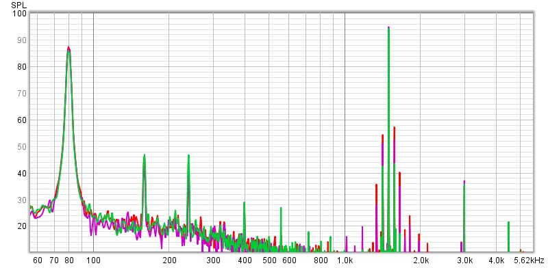
I thought some of you might find the results interesting as well, so here it is. I'm measuring at 0.5m distance. All 3 configurations are equalized to match in frequence response and level and i am using a single woofer for the 2-way test and two woofers for the 2.5 and 3-way.
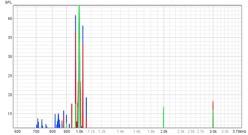
80hz and 1500hz sine wave is played simultaneously.
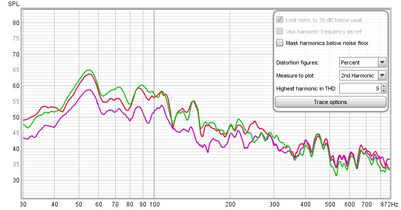
Green is 3-way LR24@400hz.
Purple is 2.5way with a 1.order lowpass at 300Hz.
Red is one woofer fullrange with BSC.
overview:
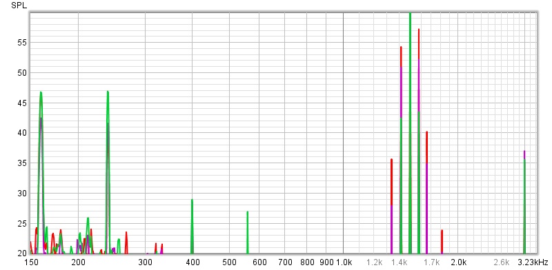
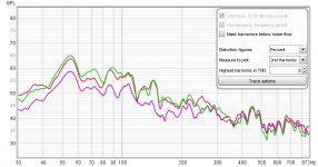
zoomed in:
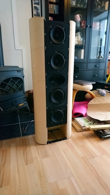
speaker: (only upper two woofers in use)
Any thoughts? Doppler distortion is very apparent in both 2.5 an 2-way. Is this an audible phenomenon?
I'm trying to find the differences in distortion between 2-way, 2.5-way and 3-way configuration for my new WMTMW or MTM project.
I thought some of you might find the results interesting as well, so here it is. I'm measuring at 0.5m distance. All 3 configurations are equalized to match in frequence response and level and i am using a single woofer for the 2-way test and two woofers for the 2.5 and 3-way.
80hz and 1500hz sine wave is played simultaneously.
Green is 3-way LR24@400hz.
Purple is 2.5way with a 1.order lowpass at 300Hz.
Red is one woofer fullrange with BSC.
overview:
zoomed in:
speaker: (only upper two woofers in use)
Any thoughts? Doppler distortion is very apparent in both 2.5 an 2-way. Is this an audible phenomenon?
Attachments


Last edited:
Very interesting result, and rather what I expected... 3 way is better than a 2.5 way, and a 2.5 way is better than a 2 way. it's nice to have quantifiable data to back up expectations.
With mechanical transducers, IM distortion, FM distortion, and doppler distortion are all interrelated, and from what I understand, are all different ways of measuring the same physical error. Thank you for the data.
With mechanical transducers, IM distortion, FM distortion, and doppler distortion are all interrelated, and from what I understand, are all different ways of measuring the same physical error. Thank you for the data.
The 2.5-way shines in the low end, where it benefits from more surface area doing the same task. Here is a comparison of the 2nd harmonic. In this very case up to 10db lower 2nd harmonic below around 250hz. However the doppler distortion is down 14db at 1580hz and 23db at 1660hz on the 3-way vs 2-way.
Attachments
Last edited:
Very nice, please share whatever you measure! I restricted myself to a 2-way topology for my coming speakers and am even going to stress the woofer further, EQ-ing the bottem end, either a Linkwitz-Transform sealed box or a 6th-order PEQ boost vented enclosure. So naturally, I did ask myself whether I should limit cone excursion and trade group delay (PEQ boost-cut) or limit group delay and trade cone excursion (intermodular/doppler distortion). I am not expecting to avoid negative impact on sound quality but what is more acceptable.
I did ask for advice here:
too small box, active assists
If your setup allows for further variations (is this happening active?) and your motivation for further test runs, I would find it interesting to see how much in a 2-way 2-tone test at 30Hz/1000Hz (deep bass / mids), additional cone excursion with bass EQ will add distortion compared to a regular response.
I did ask for advice here:
too small box, active assists
Is there measurements available on the impact of LT/Low-Boost EQ on distortion? I would like to see the rate to which it is rising with increase of Xmax and power. I suppose cone excursion will affect higher frequencies as distortion, what sort of distortion? Intermodular? The vented version can be louder but it has a much higher group delay which may be audible, although it is reaching critical levels very low and exceeds them at the limits of low-frequency audibility for Humans.
If your setup allows for further variations (is this happening active?) and your motivation for further test runs, I would find it interesting to see how much in a 2-way 2-tone test at 30Hz/1000Hz (deep bass / mids), additional cone excursion with bass EQ will add distortion compared to a regular response.
The woofers are SB17NBAC in separate 10L round boxes with semi-open backs/aperiodic vent-ish.
I can test 2 vs 3 way, 30hz/1000Hz for you. With and without bafflestep needed for the 2-way. Which in this case is about 4db shelf boost below 300Hz.
My takeaway from this test is that i will go for a 3-way. I didn't know that the doppler distortion was so severe.
I can test 2 vs 3 way, 30hz/1000Hz for you. With and without bafflestep needed for the 2-way. Which in this case is about 4db shelf boost below 300Hz.
My takeaway from this test is that i will go for a 3-way. I didn't know that the doppler distortion was so severe.
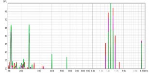
Distortion increased by 4-5db at 1030hz with a 4db boost at 30hz.
green is 3-way, and acts as a baseline to elimit the electronics own imd.
red is 2-way with no boost
blue ise 2-way with a 4db low-shelf at 400hz.
green is 3-way, and acts as a baseline to elimit the electronics own imd.
red is 2-way with no boost
blue ise 2-way with a 4db low-shelf at 400hz.
Attachments
Last edited:
I would say that harmonic or intermodulation distortion in a speaker is one of the least important measurements. Reducing them without inviting other compromises is good engineering though.Any thoughts? Doppler distortion is very apparent in both 2.5 an 2-way. Is this an audible phenomenon?
I would say that getting the directivity right and making the speaker couple with the room better will be much more important in the overall system. EQ'ing the speaker in room to deal with modal issues and avoiding the worst of them through placement of speakers and drivers will dwarf anything that distortion can bring.
Given the drivers you have a layout like the Elsinore could work quite well, worth looking at that as an option.
I have decided to go forward with a wmtmw using sb17nbac. The main target is a 3-way, but i will be open to do a 2.5-way if it measurably improves room loading, and the advantages of increased surface area in the bass supersedes the advantages of lower doppler distortion. The Elsinore-project is definatly inspiring and relevant!
Thank you very much skogs!Distortion increased by 4-5db at 1030hz with a 4db boost at 30hz.
green is 3-way, and acts as a baseline to elimit the electronics own imd.
red is 2-way with no boost
blue ise 2-way with a 4db low-shelf at 400hz.
Can you also tell me what is intermodulation and what is doppler in your charts? In #4 you where talking about doppler being down but I could not see it.
You can investigate with Vituix quite easily to see the difference in directivity between variations in driver layout. By adding in room reflections you can get some idea of what could happen in room.I have decided to go forward with a wmtmw using sb17nbac. The main target is a 3-way, but i will be open to do a 2.5-way if it measurably improves room loading, and the advantages of increased surface area in the bass supersedes the advantages of lower doppler distortion. The Elsinore-project is definatly inspiring and relevant!
The WMTMW will have much narrower vertical directivity which may or may not be what you want and there will be some lobing from the increased CTC spacing. The Elsinore layout has the advantage of reducing the CTC between the mid and waveguide and having the line of woofers below will mitigate the floor bounce by smoothing it out.
Narrowing the vertical directivity from the WMTMW will also help with the floor and ceiling reflections.
More cone area for low frequencies is always a good idea and if you want high SPL's the increased cone area reducing excursion could well offset a general increase in distortion from band limiting. Worth testing at different SPL's to see the effect.
You can investigate with Vituix quite easily to see the difference in directivity between variations in driver layout. By adding in room reflections you can get some idea of what could happen in room.
The WMTMW will have much narrower vertical directivity which may or may not be what you want and there will be some lobing from the increased CTC spacing. The Elsinore layout has the advantage of reducing the CTC between the mid and waveguide and having the line of woofers below will mitigate the floor bounce by smoothing it out.
Narrowing the vertical directivity from the WMTMW will also help with the floor and ceiling reflections.
More cone area for low frequencies is always a good idea and if you want high SPL's the increased cone area reducing excursion could well offset a general increase in distortion from band limiting. Worth testing at different SPL's to see the effect.
I've been worried about the ctc, but it looked liked the Elsinore had an even larger ctc. The ctc of the mids are now 31cm in my design. The Elsinore's ctc looks to be 38cm. Elsinore Construction
The tweeter and waveguide can handle LR24 at 1600Hz, but i'm hoping 1900Hz will sound good. That will yield the best horizontal dispersion as well as reduce imd from the tweeter.
The main reason for the wmtmw alignement is to get the tweeter on a similar height as the center channel, which is under the tv.
Last edited:
Thank you very much skogs!
Can you also tell me what is intermodulation and what is doppler in your charts? In #4 you where talking about doppler being down but I could not see it.
Not sure if i use the term correctly. I mean the distortion the pops up at x*F1+/-F2 when playing two tones. So 30hz + 1000Hz = 1030Hz or 2*30Hz + 1000Hz = 1060Hz or 30Hz - 1000Hz = 970Hz and so on.
Did you hit distortion tab in REW for this?
I read some about where intermodulation kicks in here
Speakers: Principles
I read some about where intermodulation kicks in here
Speakers: Principles
Did you hit distortion tab in REW for this?
I read some about where intermodulation kicks in here
Speakers: Principles
Nope, i used RTA.
That is intermodulation distortion, IMD.Not sure if i use the term correctly. I mean the distortion the pops up at x*F1+/-F2 when playing two tones. So 30hz + 1000Hz = 1030Hz or 2*30Hz + 1000Hz = 1060Hz or 30Hz - 1000Hz = 970Hz and so on.
IMD is created when two or more audio tones beat with one another (intermodulate) in a non-linear device to produce undesired new tones. The primary mechanism producing IM in most devices is AM (amplitude modulation), which creates sidebands that are at the sum and difference of the frequencies of the original audio tones.
AM distortion is often mistakenly called "Doppler distortion".
From Rod Elliot:
Doppler Distortion in loudspeakers
"That the phenomenon of the Doppler effect is real is not in question - what is in question is whether the same effect occurs in a loudspeaker reproducing more than a single tone simultaneously. Furthermore, we should clarify the term 'distortion', since the word is normally applied to a non-linear function. Should the effect be demonstrated to exist in a loudspeaker, then it is obvious that it will appear in an ideal (or theoretically perfect) driver as well, so there is no non linearity. Based on this, the effect probably should not be called 'distortion' (although it must be said that anything that adds frequencies that did not exist in the original recording actually is distortion, but that is probably a philosophical debate rather than one to be considered by the engineering fraternity).
The first thing to consider is the maximum velocity of a loudspeaker cone, when driven by a signal of any given frequency. This is generally much lower than we might imagine, and the velocity may be calculated by ...
Vp = 2π × fL × Xp[ 2 ]
where Vp is the peak cone velocity, fL is the low frequency and Xp is cone displacement. For example, a cone that is moving ±5mm (10mm total) at a frequency of 50Hz will have a peak velocity of 3.14m/s (11.3km/h) - this is certainly not fast, and in itself would account for a rather small frequency shift. In a system where (conventional velocity based) Doppler effect does change the frequency, the change is given by ...
ΔfH = 2π × fL × fH × Xp / c[ 2 ]
where fH is the high frequency (modulated) tone and c is the velocity of sound (nominally 343m/s). Using the velocity calculated earlier, we get a shift of 9.1Hz for a high frequency tone of 1kHz (less than 1%). Bear in mind though, that the rate of change needs to be maintained for a reasonable period of time before the frequency shift will become apparent, and 10ms (the time it takes a 50Hz signal to swing from maximum positive to maximum negative) is probably insufficient to cause an audible frequency shift. Our hearing is such that it needs a reasonable number of cycles (which varies with frequency) before we can identify the pitch of a tone.
Remember that for the (conventionally explained) Doppler effect to exist, the 'carrier' (vehicle, train, etc.) or listener must be moving through the medium, but a loudspeaker cone does no such thing. The medium (air) will be pushed outwards and sucked inwards by the low frequency movement of the cone, so there is no (or very little) relative movement between them - the medium is moving with the cone! What is heard (and most commonly incorrectly attributed to Doppler effect) is a combination of things (in descending order of importance) ...
Intermodulation distortion
Amplitude modulation
Phase shift
Of these, the only one that comes close to frequency modulation (as predicted by much existing theory and practice) is phase shift, and this is caused by the relative position of the cone at any instant in time in relation to the listener. That the shift is small is obvious, and equally obviously it depends on the peak to peak travel of the cone. Assuming a large cone movement for the low frequency signal of (say) 10mm in each direction, this represents a complete cycle (360°) shift at 34,500Hz, or 36° at 3,450Hz (for example). It must be considered that any loudspeaker that is expected to have anywhere near 20mm travel at low frequencies, and is expected to reproduce high frequencies as well, will almost certainly generate considerable intermodulation of the higher frequencies.
Interestingly, the phase shift observed will be exactly the same at DC as at any low frequency that causes the same displacement - even moving the whole box relative to the microphone will generate the same amount of (static) phase shift. This is simply a function of the velocity of sound in air, and the wavelength of the high frequency tone. A 10mm change in the position of the box will cause a 36° phase shift (of a 3,450Hz tone) in exactly the same way that 10mm of cone movement will - this is a simple physical relationship.
An interesting effect of amplitude modulation (within the range we can expect from a loudspeaker) is that when you hear it, it sounds like frequency modulation. Again, this is a well known effect, and references abound. The effect is caused by the way our hearing works, and this may be the predominant effect that is heard by listeners who have 'proven' that Doppler distortion exists because they have 'heard' it. In general, the pitch seems to reduce slightly as amplitude is increased for frequencies below around 2kHz, while for frequencies above 2kHz the pitch increases with increased amplitude."
At any rate, IMD, AM or phase shift at the at the levels you reported in the OP would be difficult to hear, but when a driver exceeds Xmax at low frequencies and is reproducing high frequencies, IMD and AM distortion can easily be heard, sounding like the vocalist is "gargling", no measurement needed ;^).
Art
Last edited:
I would want to have the tweeter as close to seated ear height as possible in the left and right speakers. If the centre has to be low to go under the TV then that is unavoidable but I wouldn't want to mirror that problem if you don't need to in the main speakers. Unless the waveguide has been designed to be listened to vertically off axis?The main reason for the wmtmw alignement is to get the tweeter on a similar height as the center channel, which is under the tv.
Being elliptical the vertical pattern control will give out much sooner than the horizontal.
You could still have a nice 3 way arrangement with the waveguide on top and all the woofers in a line below.
The Elsinore layout has the advantage of reducing the CTC between the mid and waveguide and having the line of woofers below will mitigate the floor bounce by smoothing it out.
But having the woofers above and below mids and tweet will this not have the same effect plus the advantage to smooth out floor-ceiling coupling?
I would want to have the tweeter as close to seated ear height as possible in the left and right speakers. If the centre has to be low to go under the TV then that is unavoidable but I wouldn't want to mirror that problem if you don't need to in the main speakers. Unless the waveguide has been designed to be listened to vertically off axis?
Being elliptical the vertical pattern control will give out much sooner than the horizontal.
You could still have a nice 3 way arrangement with the waveguide on top and all the woofers in a line below.
They will be angled 7deg back to get the tweeter on axis.
- Status
- This old topic is closed. If you want to reopen this topic, contact a moderator using the "Report Post" button.
- Home
- Loudspeakers
- Multi-Way
- Testing 2-way vs 2.5-way vs 3-way IMD