if you had phase measured from an appropriate distance, why would you interested in the actual delay?
I don't know... I did not dream this method up, I am not that clever... I got it from someone on this forum.
I very recently went through this exact exercise. I can post the Xsim file to demonstrate what I am talking about.
I know this method is around and I have my theories. I recall one time Jeff Bagby used it to work around a difficult situation, and some have been assuming it should always be done that way. Then there's the idea that simulators have the ability to adjust delay, so it should be used, however it's primarily expected to be used by those using factory measurements.
I don't blame anyone for being overwhelmed.
What some do questionably is to use this method to "reset" phase.
I don't blame anyone for being overwhelmed.
Deriving minimum phase is what you do when a manufacturer gives you a response plot without phase information, and it is presumed to be primarily minimum phase."measured phase" and "derived phase"
What some do questionably is to use this method to "reset" phase.
Minimum phase can only be 'extracted' from an impulse response, and not from a frequency response plot. Once an impulse response has been 'flattened' into a frequency response plot, the information has been degraded, and proper phase information cannot be restored.
Maybe I'm using the wrong terms. HBT extracted phase? Are you saying this is not possible from the FR response? I thought it very much is given drivers are minimum phase devices?
The accuracy of the transform isn't a problem... 'Extracting' suggests that there's something in there somewhere, but for a frequency response plot without phase there is no way to know how it was composed, there is no information. If there was pure delay, the transform will take you back to the source, but there is no way to recognise excess phase components, and they are interpreted differently.
Largely, yes. Without going too deep, there's diffraction components and reflections (including internal/external cabinet reflections).given drivers are minimum phase devices
if you had phase measured from an appropriate distance, why would you interested in the actual delay?
I suppose in my case I am primarily interested in active speaker design with DSP filtering. The DSP software I use explicitly requires the z-offset delay values for each driver.
My measuring equipment (Omnimic) records amplitude and phase when capturing an FRD curve, but it does not capture absolute phase (if that is the right term) from one sweep to the next. So if I measure a woofer and a tweeter, even though I maintain the same mic position and the same input signal, I will not get “phase alignment” between the two drivers. The software documentation acknowledges this.
The software has a functionality to determine driver z-offset, but it seemed cumbersome to me, so I adopted the Xsim method. I do not remember who described it to me first, perhaps jReave, XRK971, Linesource, System7, or Wintermute… not sure... One of the talented circuit designers.
I have confirmed that when I use this method to determine z-offset, I can make a LR4 crossover and reverse the polarity of the tweeter and measure a very deep null… 30 to 40 dB. If I then alter the digital time delay and optimize the depth of the null, I find that the value is within 3 or 4 mm of the value produced by Xsim simulation.
Last edited:
Dave Bullet wrote:
Perhaps "extracting minimum phase" is what I do without being aware of it?
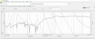
The first FR curve is of a tweeter i recently measured. The FR response goes down below 20 Hz, which is nonsense... the mic was picking up ambient noise of course. If I view the FRD file in notepad, I see the first entry is 4.39 Hz. None of this would seem to matter, but it results in the phase wraping over and over again, which seems odd.
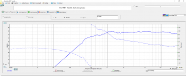
The next FR curve has been "phase restored" by the Omnimic software. I cut off the response at 300 Hz, and forced the response along an assumed 12 dB/octave roll off (which matches the OEM curve). When I do this, the phase data "resets". To my limited understanding, it seems the phase data in the first curve was pegged (or linked) to 4.39 Hz, and the phase data in the second curve is pegged to 300 Hz. The phase plot seems much more useable now, and more meaningful.
When I designed a pair of passive 2-ways over the summer, I confirmed to myself that Xsim produced the same simulation whether I used the "as measured" phase, or the corrected phase. And this makes sense, because in my simplistic understanding, phase is just the relative time delay between two frequencies expressed as a phase angle instead of microseconds. The time delay is not changing, just the frequency we are pegging to.
So when I use the "phase restore" feature of Omnimic, am I extracting minimum phase?
You require a Z offset when either:
a) you are using manufacturer graphs with extracted minimum phase
b) you re-measure then (for whatever reason - say splicing a nearfield response) re-extract minimum phase
If you are using phase from a measurement and have not moved the mic between measurements across your drivers - then you would use a zero Z offset
Perhaps "extracting minimum phase" is what I do without being aware of it?
The first FR curve is of a tweeter i recently measured. The FR response goes down below 20 Hz, which is nonsense... the mic was picking up ambient noise of course. If I view the FRD file in notepad, I see the first entry is 4.39 Hz. None of this would seem to matter, but it results in the phase wraping over and over again, which seems odd.
The next FR curve has been "phase restored" by the Omnimic software. I cut off the response at 300 Hz, and forced the response along an assumed 12 dB/octave roll off (which matches the OEM curve). When I do this, the phase data "resets". To my limited understanding, it seems the phase data in the first curve was pegged (or linked) to 4.39 Hz, and the phase data in the second curve is pegged to 300 Hz. The phase plot seems much more useable now, and more meaningful.
When I designed a pair of passive 2-ways over the summer, I confirmed to myself that Xsim produced the same simulation whether I used the "as measured" phase, or the corrected phase. And this makes sense, because in my simplistic understanding, phase is just the relative time delay between two frequencies expressed as a phase angle instead of microseconds. The time delay is not changing, just the frequency we are pegging to.
So when I use the "phase restore" feature of Omnimic, am I extracting minimum phase?
Attachments
The term "extract minimum phase" is an anomaly, and has no real meaning. It was started by the DIY speaker crowd. A web search for the term in quotes should demonstrate that.
Whether you wind it back yourself until it looks free of delay, or you wind it until your acoustic result looks useable, all you are doing is adjusting delay. Provided you have a reason for doing that it is a valid method.I suppose in my case I am primarily interested in active speaker design with DSP filtering. The DSP software I use explicitly requires the z-offset delay values for each driver.
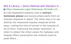
Among the search results, here is one from the Audio Engineering Society from 2004, which I would expect to be reasonable. It talks about separating minimum phase from excess phase components in an impulse response. The author displays an understanding.
Note that close to nobody here does that, for any reason at any time. This has become conflated with the process of deriving phase from a response plot based on the assumption it applies as minimum phase. Its first incorrect use seems to be with one of the old FRD tools, from where it filtered down to audio amateurs.
Note that close to nobody here does that, for any reason at any time. This has become conflated with the process of deriving phase from a response plot based on the assumption it applies as minimum phase. Its first incorrect use seems to be with one of the old FRD tools, from where it filtered down to audio amateurs.
Attachments
- Status
- This old topic is closed. If you want to reopen this topic, contact a moderator using the "Report Post" button.
- Home
- Loudspeakers
- Multi-Way
- Crossover Review