I was always impressed with the sound and looks of speakers from the 70s.
They were effective, simple, easy on the eye and had a logical driver placement for 3 way systems with larger bass drivers than what we typically see today. Speakers of this era also had a lot more enjoyable "body" most likely due to the larger bass drivers and wider baffles, compared to today's narrow floor standing towers which I never liked. Which is one of many reasons I'm into DIY, I want to create similar sounding speakers but with more up to date technology and driver quality.
My first pair of speakers as kid was an inherited SEAS/Dynaco A25 DIY kit of some variant. Later I was playing around with Pioneer CS-R700. Both I really enjoyed. Since then Ive made many different types of budget DIY projects, last few including Fane full range PA drivers and Eminence coaxials. Now I'm trying to design some similar looking speakers from the 70s era and I'm playing around with baffle sizes and driver selection, and the use of the golden ratio and Fibonacci sequence numbers as it seems speakers close to this baffle ratio is what I seem to enjoy, looking at the sizing specs of those good 70s designs, I can name a bunch but you get the idea.
I want to go up a size though to fill a larger basement with high efficiency dynamics and will for the most part use PA drivers. Im already playing around with some 12" coax designs but will go further in my next project once I get the experience with crossovers and box woodwork finishing as my older project never looked very good, and Ive always struggled with crossover due to lacking measuring tools and know-how so I need to step up the game before going into this big project.
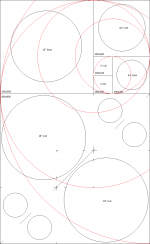
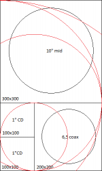
The current idea however, is a big speaker system based on the drawing attached 1300x800mm front baffle, using the first few Fibonacci numbers to determine the driver placements, in this case a 4 way system with active sub section. I will most likely build the sub section as a stand alone 800x800 box but in the drawing shown as one speaker. I may also just drop the whole sub section and go with 800x500 3-way system as it may be more than enough for my use. I'm also going to make a smaller 10" three way system for a different room using the same layout, might make this first for practise.
Any one else using the golden ratio of phi for designing their speakers?
They were effective, simple, easy on the eye and had a logical driver placement for 3 way systems with larger bass drivers than what we typically see today. Speakers of this era also had a lot more enjoyable "body" most likely due to the larger bass drivers and wider baffles, compared to today's narrow floor standing towers which I never liked. Which is one of many reasons I'm into DIY, I want to create similar sounding speakers but with more up to date technology and driver quality.
My first pair of speakers as kid was an inherited SEAS/Dynaco A25 DIY kit of some variant. Later I was playing around with Pioneer CS-R700. Both I really enjoyed. Since then Ive made many different types of budget DIY projects, last few including Fane full range PA drivers and Eminence coaxials. Now I'm trying to design some similar looking speakers from the 70s era and I'm playing around with baffle sizes and driver selection, and the use of the golden ratio and Fibonacci sequence numbers as it seems speakers close to this baffle ratio is what I seem to enjoy, looking at the sizing specs of those good 70s designs, I can name a bunch but you get the idea.
I want to go up a size though to fill a larger basement with high efficiency dynamics and will for the most part use PA drivers. Im already playing around with some 12" coax designs but will go further in my next project once I get the experience with crossovers and box woodwork finishing as my older project never looked very good, and Ive always struggled with crossover due to lacking measuring tools and know-how so I need to step up the game before going into this big project.
The current idea however, is a big speaker system based on the drawing attached 1300x800mm front baffle, using the first few Fibonacci numbers to determine the driver placements, in this case a 4 way system with active sub section. I will most likely build the sub section as a stand alone 800x800 box but in the drawing shown as one speaker. I may also just drop the whole sub section and go with 800x500 3-way system as it may be more than enough for my use. I'm also going to make a smaller 10" three way system for a different room using the same layout, might make this first for practise.
Any one else using the golden ratio of phi for designing their speakers?
Attachments

Last edited:
This kind of alignment is not that good as you may think. The best is to keep all in a more or less vertical line and drivers close to each other.
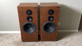
I agree that wider baffles and bigger woofers tend to sound better, but fashion decided that speakers must be as small as possible... I would keep it more like Harbeth or these JBL L100T does (see picture), and keep everything vertical line, but mid and tweeter slightly offset from the center. If you don't keep that alignment you mess up the vertical imaging of the speaker box.
I agree that wider baffles and bigger woofers tend to sound better, but fashion decided that speakers must be as small as possible... I would keep it more like Harbeth or these JBL L100T does (see picture), and keep everything vertical line, but mid and tweeter slightly offset from the center. If you don't keep that alignment you mess up the vertical imaging of the speaker box.
Attachments
Larger baffles can keep you in half space, for reduced lower-midrange room interaction, which can be tricky to remedy, because the preferred way to deal with baffle step is to have none.
However for dealing with the baffle edges you could consider rounding them over instead.
However for dealing with the baffle edges you could consider rounding them over instead.
Setting up the drives in vertical alignment makes sense in midrange and tweeter but I guess it’s less of a problem for the 15”? I’ll play around some more with the design and driver selection, coax may be overkill as well. May try open baffle first just to get a picture of the mids and adjust performance before building the whole thing.
To elaborate on this, the drivers should be aligned vertically so there is no alteration of path lengths (and resultant dips/nulls) when you are listening horizontally off-axis. That is of course unless for some reason the application demands that the vertical off axis response be more important than the horizontal.This kind of alignment is not that good as you may think. The best is to keep all in a more or less vertical line and drivers close to each other.
Additionally, you're best off locating the midrange and tweeter closer to one edge of the baffle as to make the edge diffraction from the left and right edges cancel (or whichever two edges of the baffle are closest). The golden ratio does dictate the ideal amount of offset here, but the size of the drivers and distances from the top and bottom edges also come in to play, since the diffraction from all 4 edges should ideally cancel as much as possible. I'd recommend 'The Edge' to find the ideal baffle layout rather than relying on rules of thumb.
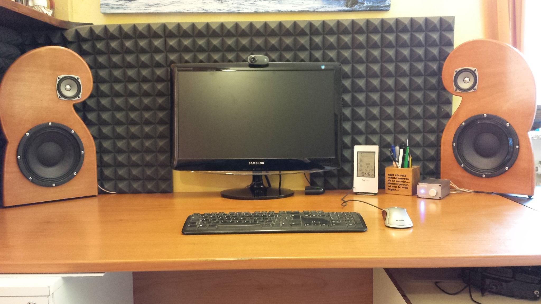
Here's a speaker I built. The tweeter is first positioned to achieve the smoothest response. Coincidentally the distance from the centre of the tweeter to the second closest edge is around 1.6x (golden ratio) that of the closest edge distance. The third edge is around 1.6x the second edge distance.
The mid is positioned directly underneath the tweeter. The woofer is then positioned directly under the midrange - of course it must be horizontally misaligned in my design due to the width of the cabinet, however at the woofer-mid crossover frequency the wavelength is sufficiently long that baffle step and path length differences have minimal effect.

Finally, if you apply any roundovers to your baffle edges, consider that the baffle is effectively smaller by half the roundover radius. I.e. if you make a baffle that is 200x400mm, then apply a 10mm radius roundover to the left and right edges, you've effectively narrowed the baffle by 5mm on each side, so now you should simulate it as if it were 190x400mm.
Last edited:
Indeed, offsetting the tweeter will make the frequency response more linear but only on axis, offaxis the response can go worse. one should consider many dimensions when dealing with driver layout
Setting up the drives in vertical alignment makes sense in midrange and tweeter but I guess it’s less of a problem for the 15”? I’ll play around some more with the design and driver selection, coax may be overkill as well. May try open baffle first just to get a picture of the mids and adjust performance before building the whole thing.
You should try out a simulation software like the edge from tolvan.com which is very simple to use
" bigger woofers tend to sound better" - depends on the woofer.... 'HiFi' woofers usually have better low bass, but moderate efficiency; "PA" woofers are efficient, but generally, if they can play low at all, require a huge box.....
of course, there are exceptions to every rule, the trick is to find them 🙂
of course, there are exceptions to every rule, the trick is to find them 🙂
A DSP can fix most of the "efficient woofers need huge boxes" problem fairly easily. But once you go down the DSP rabbit hole you'll end up going full active (multiple amps, etc.). Personally I don't find that a problem but some do.
I did a thorough analysis on baffle diffraction a while back (How to tame your diffractions). To summarize my findings: the ideal baffle shows a distance between edge and tweeter of x to one side, 2*x to the next side, 3*x to the third side and 4*x to the fourth side. It has rounded edges with a radius of at least r=x/(1+pi/2). With x in the range of about 5 cm you could conveniently build a shelf speaker.
You already pointed out that tweeter and midrange should be vertically aligned and as close as possible to each other.
There will always be a single angle under which the diffraction pattern is worst. That alignment is reached when the distance tweeter-left edge-listener is equal to tweeter-right edge-listener. If the tweeter is centered, that angle is on-axis in front of the speaker. If the tweeter is offset, it will be reached when the speaker is tilted so that the shorter edge is moved away from the listener and the larger edge is moved towards the listener. To me the second option sounds much more appealing since then the direct sound is cleaner and only reflections suffer from deviations.
You already pointed out that tweeter and midrange should be vertically aligned and as close as possible to each other.
Indeed, offsetting the tweeter will make the frequency response more linear but only on axis, offaxis the response can go worse. one should consider many dimensions when dealing with driver layout
There will always be a single angle under which the diffraction pattern is worst. That alignment is reached when the distance tweeter-left edge-listener is equal to tweeter-right edge-listener. If the tweeter is centered, that angle is on-axis in front of the speaker. If the tweeter is offset, it will be reached when the speaker is tilted so that the shorter edge is moved away from the listener and the larger edge is moved towards the listener. To me the second option sounds much more appealing since then the direct sound is cleaner and only reflections suffer from deviations.
The third option is to try to balance the reflected energy with the direct energy. In addition, trying for a reduction in diffraction.
In this post (the last quoted part), I can demonstrate how difficult it can be balancing the direct and reflected energy.
Getting the most out of a baffle using the roundover (as opposed to the offset) technique, the driver can get the best out of the baffle being in the middle.
In this post (the last quoted part), I can demonstrate how difficult it can be balancing the direct and reflected energy.
Getting the most out of a baffle using the roundover (as opposed to the offset) technique, the driver can get the best out of the baffle being in the middle.
One thing to do is to keep as much of the distances from the drivers to the baffle edges distances different. That’s why a driver centered on a round baffle has the worst diffraction induced ripples. That’s why rectangular baffles are better than round baffles. And that’s why a driver asymmetrically offset in a rectangular baffle is one step better. Even better than this is something more organic like a Fibonacci spiral where there are no two distances that are alike. Or a flower petal baffle. I find that a trapezoid works very well too. It’s measurable and easy to show. Round overs make a huge difference. Perfectly flush mounted rebates for tweeters and mid ranges also make a big difference. Even a 1mm thick lip around a tweeter is measurable as excess ripple.
Fibonacci:
Open baffle Nautilus: the Fibonacci solution to edge diffraction
Flower Petal:
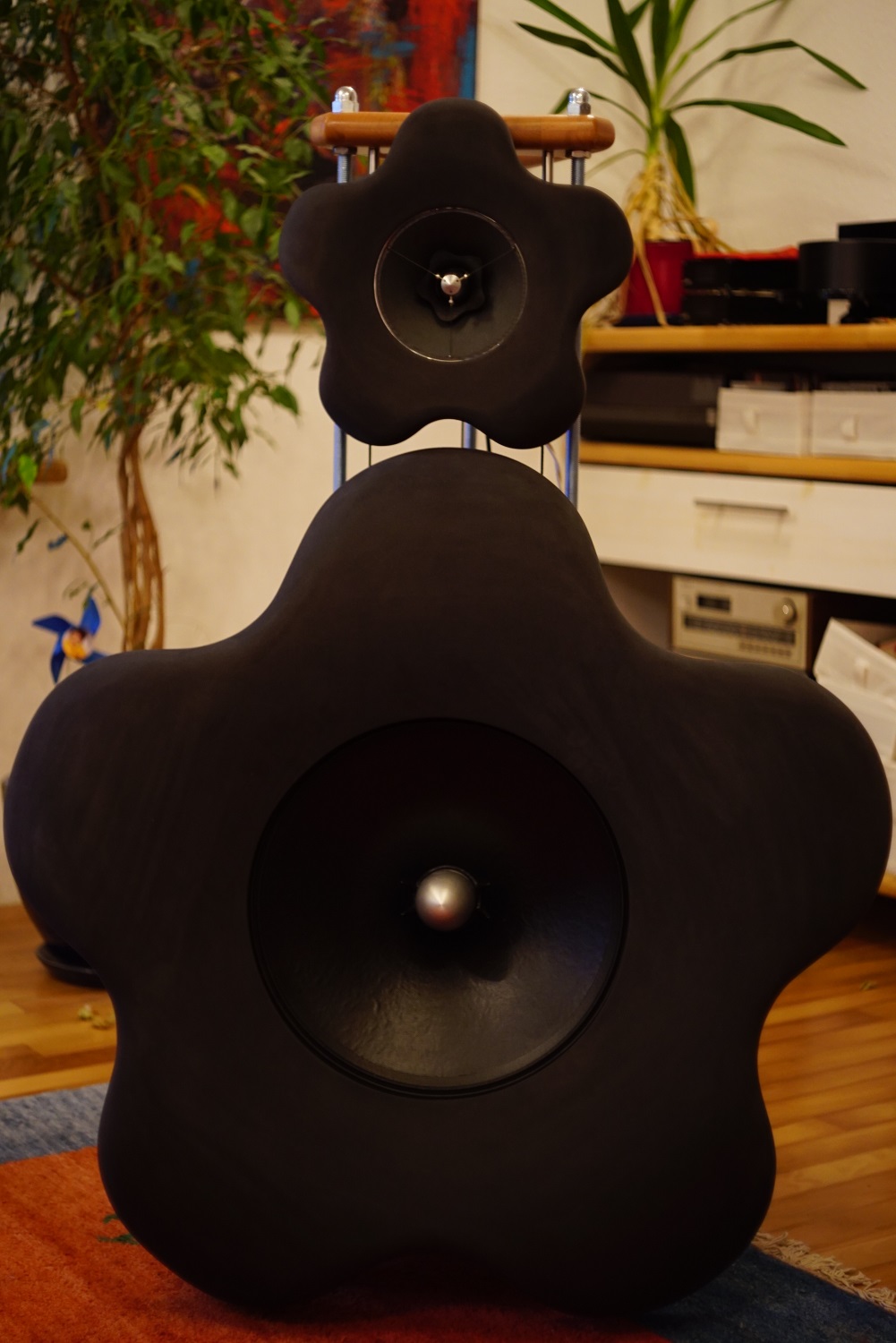
EVA foam for performance speaker enclosures
Siegfried Linkwitz’s discussion on baffle shape and effects on diffraction:
http://www.linkwitzlab.com/diffraction.htm
Here is baffle diffraction for a circle:
vs rectangle:
Fibonacci:
Open baffle Nautilus: the Fibonacci solution to edge diffraction
Flower Petal:
EVA foam for performance speaker enclosures
Siegfried Linkwitz’s discussion on baffle shape and effects on diffraction:
http://www.linkwitzlab.com/diffraction.htm
Here is baffle diffraction for a circle:
vs rectangle:
Last edited:
If it gets to this, I'd refer you to post #6 by celef.xrk971 said:It’s measurable and easy to show.
The work behind these baffles is impressive, the calculations and the build.
Vintage speakers usually look very nice with their classic proportions and have a warm full-bodied character. But there are some things we know today that we didnt know then (or didnt pay attention to)
-Always put the drivers in a vertical array, this will improve horisontal dispersion.
-Dont use more than one tweeter next to each other and pointing in the same direction. Several drivers next to each other will produce comb-filter effects.
-The optimal distance to cabinet edges can be simulated in the free software "the edge": Tolvan Data
Last edited:
Even a 1mm thick lip around a tweeter is measurable as excess ripple.
Ah, but would you hear it?
That's why I like the flower approach. What would be the best "petal" shape?If it gets to this, I'd refer you to post #6 by celef.
No, sims, not measurements in the thread X linked to https://www.diyaudio.com/forums/ful...rmance-speaker-enclosures-38.html#post5593040 Oh, here we go, I jumped the gun... https://www.diyaudio.com/forums/ful...rmance-speaker-enclosures-40.html#post5594879
Last edited:
What do you expect that we can make of these measurements? Perhaps you should define 'best', I'm still not sure what we're talking about.
- Home
- Loudspeakers
- Multi-Way
- In search of the perfect baffle