80Hz subwoofer crossover is a THX standard designed for movie theaters. Your room isn't that big. You'll lose low frequency localization at room transition frequency when long sound waves are bouncing around the room many times from many different directions before your brain even recognizes what it's hearing.
Movie theater =/= home theater.
Your center channel will come down to directivity: wide vs narrow. Narrow commonly includes a deep waveguide on the tweeter like a Klipsch. Wide *usually* does not include a waveguide or they have shallow waveguides. Large space movie theaters will use waveguides to cover a large audience with sufficient listening volume efficiently. Small space home theaters will use waveguides to keep early reflections off ceilings, floors, and side walls. Same device different goals. Both wide and narrow directivity work but the choice to go one way or the other impacts what you do with your room space.
If you have a wide directivity center channel you might want to treat the side walls. If you have narrow directivity you might want to treat the rear walls. Reflections can screw with your comprehension of dialogue. That's why headphones make movie dialogue so easy to understand, zero confounding reflections.
If you're building a home theater dialogue intelligibility is above all. Unless you like to watch movies with closed caption.
Here's a thought - if you are having trouble letting go of the front soundstage voice matching idea you might think about just biting the bullet on the RS75's. If you got them from Parts Express not too long ago, they have a good return policy so you might try that. Or if you want to continue to build speakers, they could make a decent little TM or MTM computer speaker for yourself or someone you know.
Then I would pick up 2 more RS150's and 2 more RS100's. Now you can make matching (as close as possible anyways) 3-way CC and L&R channels. The CC would still be W(T/MM)W and the L&R would be MTMWW with the mids now the RS100's and the woofers now the RS150's.
You'll achieve 3 things with this:
- max SPL will be increased by using larger drivers in the CC
- better intelligibility of the CC is maintained with a 3-way
- you'll get the best timber matching between your front speakers as possible.
The CC of course will need to be a little taller. I'm guessing about 9" x 26"-30" for the front baffle. And I guess your brother has to also be content with a little higher costs.
Just a thought anyways.
Thank you again for the honest help. But yeah, what I need right now it to just learn as much as I can, fail, and try again. The only constraint on time right now is the weather getting colder, which will make it more difficult to cut my wood outside. But maybe I need to construct a way to gather dust in the garage better when it's winter. All-in-all, I do not plan to make sawdust soon (dont wanna rush it), yet sooner than later would not hurt.
Anyways, I do not expect you to walk with me through this process or design them for me @jReave. But every now and then, if I do not find an answer with research I will come here. And here has been very helpful!
The Troels Graveson link has been really helpful actually, and also the idea about a 3-way for the L/R has also been fun to dive into seeing how that will work. Since the CC is already a 3-way, making the L/R the same really makes logical sense for both voicing and getting a higher max SPL. Though, I'm guessing that the rear satellites will not have to be three way as well. As long as I, as close as possible, match the frequency responses.
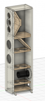
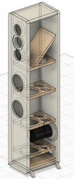
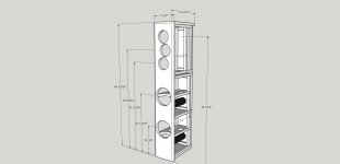
I have been doing lots of research and also reading much more of the books I have. So, recently I have got my first version of the interior of the towers, with the 3-way design. The picture is attached.
With the help of the LDC, I have picked doing the Quasi Third-Order (QB3) alignment. From that, using the Qts parameter I got from the average of all six drivers I have, I have come to a box volume, box tuning, and my F3.
So Vb is 12.88L for one speaker, so in the tower I need twice that. Using Unibox I have found that a volume of 26L-28L is adequate, accounting for any possible leaks. So, the bottom half in the tower of the woofer section has come out to a net volume of 26.5L. Taking into account the bracing, woofers, chamfers, port, and xo approximation.
I have not properly tested the midrange drivers yet, though I used the recommended volume and F# given from Dayton Audio, that was found using BassBox 6 Pro. So, with the Vb = 0.04ft3 (1.13L) and F3 = 141Hz for a sealed box.
The top volume in the tower for the midranges has been designed to make the walls unparalleled, and to achieve such a small volume without having the drivers too close to the back wall. So the final net volume is 2.37L.
Finally, with the port I have read how for a 6" speaker, a port of 2" is the minimum diameter. But a 3" diameter will be better. With that in mind and equations in the LDC, I came to a port length of 6.534". Which works well since the port is more than 3" away from the opposing front baffle.
Also, I have kept in mind how the drivers need to be closer than half the wavelength at the xo frequencies in order to not interfere with phase issues. So far, the woofers are definitely close enough (assuming the xo is around 200-300Hz or so). But for the midranges to tweeter, the minimum distance I can squeeze them together is 3.75". Which is just not close enough for a xo at 2kHz, so I will need to count my losses on that if the xo comes out to be higher. Then figure out next what to do about it, or not do about it.
I guess, to me all of the design requirements are checking out from both the LDC, Unibox, and from other insight from threads. But I am wondering if there is anything that seems like it is out of place or any spot for potential problems in this design? I have not gotten to the xo yet, but plan to do that this week. I do intend that my design might change after the xo is figured out, keep in mind this is not a final final for me.
You did say how you would be willing to simulate some xo's for me, and if you are still willing that would be a major help! If you're able to do with within your time, I simple process of how you do it would be greatly appreciated!") I know that thread you linked has a process for xo's, so I might try that soon here as well.
I know that thread you linked has a process for xo's, so I might try that soon here as well.
Anyways, I do not expect you to walk with me through this process or design them for me @jReave. But every now and then, if I do not find an answer with research I will come here. And here has been very helpful!
The Troels Graveson link has been really helpful actually, and also the idea about a 3-way for the L/R has also been fun to dive into seeing how that will work. Since the CC is already a 3-way, making the L/R the same really makes logical sense for both voicing and getting a higher max SPL. Though, I'm guessing that the rear satellites will not have to be three way as well. As long as I, as close as possible, match the frequency responses.
I have been doing lots of research and also reading much more of the books I have. So, recently I have got my first version of the interior of the towers, with the 3-way design. The picture is attached.
With the help of the LDC, I have picked doing the Quasi Third-Order (QB3) alignment. From that, using the Qts parameter I got from the average of all six drivers I have, I have come to a box volume, box tuning, and my F3.
So Vb is 12.88L for one speaker, so in the tower I need twice that. Using Unibox I have found that a volume of 26L-28L is adequate, accounting for any possible leaks. So, the bottom half in the tower of the woofer section has come out to a net volume of 26.5L. Taking into account the bracing, woofers, chamfers, port, and xo approximation.
I have not properly tested the midrange drivers yet, though I used the recommended volume and F# given from Dayton Audio, that was found using BassBox 6 Pro. So, with the Vb = 0.04ft3 (1.13L) and F3 = 141Hz for a sealed box.
The top volume in the tower for the midranges has been designed to make the walls unparalleled, and to achieve such a small volume without having the drivers too close to the back wall. So the final net volume is 2.37L.
Finally, with the port I have read how for a 6" speaker, a port of 2" is the minimum diameter. But a 3" diameter will be better. With that in mind and equations in the LDC, I came to a port length of 6.534". Which works well since the port is more than 3" away from the opposing front baffle.
Also, I have kept in mind how the drivers need to be closer than half the wavelength at the xo frequencies in order to not interfere with phase issues. So far, the woofers are definitely close enough (assuming the xo is around 200-300Hz or so). But for the midranges to tweeter, the minimum distance I can squeeze them together is 3.75". Which is just not close enough for a xo at 2kHz, so I will need to count my losses on that if the xo comes out to be higher. Then figure out next what to do about it, or not do about it.
I guess, to me all of the design requirements are checking out from both the LDC, Unibox, and from other insight from threads. But I am wondering if there is anything that seems like it is out of place or any spot for potential problems in this design? I have not gotten to the xo yet, but plan to do that this week. I do intend that my design might change after the xo is figured out, keep in mind this is not a final final for me.
You did say how you would be willing to simulate some xo's for me, and if you are still willing that would be a major help! If you're able to do with within your time, I simple process of how you do it would be greatly appreciated!
I know that thread you linked has a process for xo's, so I might try that soon here as well.Attachments
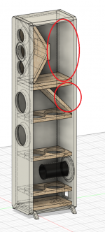
Excellent. That is much further along than where you started. No glaring errors that I can see. But a few suggestions follow:
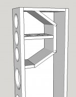
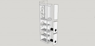
- you've got a bit of wasted space in the design. See the pic below, circled in red. All of that space could be used for the woofers, not that you need any more but if you made some adjustments in dimensions, the cab could be smaller overall.
- just as egs, you could raise the bottom panel the way Troels frequently does and put the xo in there. Or do the same sort of thing behind the mid chamber instead. You could also increase the size of the mid chamber too if you wanted to.
- re the mid chamber: in a 3-way where you are going to low pass the mids anyway, the alignment in relation to F3 becomes sort of irrelevant. Instead it's more important to have a chamber that is large enough to accommodate enough insulation to absorb the backwave and leave room for the driver to breath, and in my mind to not over tighten the air spring of the sealed chamber. Depending on the intended xo point I might choose a minimum of 3-4L per driver. More for a lower xo point. Less for a higher one. If you are going with the RS100's as your mids, note that Unibox suggests a vented alignment. That probably means that it has somewhat of a stiff suspension. So if you stick it into a small sealed box, that results in a stiff suspension to start and then a stiff box suspension as well. Not ideal. I see a larger chamber as better in this situation. Sometimes an aperiodic alignment can work out well too if space is tight or if the impedance peak is quite high which can be trouble for the xo and which the aperiodic design diminishes. You'll find Troels uses the aperiodic mid enclosure quite frequently. I do like the inverted cone shape of the mid chamber for the mids though. Maybe make it deeper though.
- the LDC is considered one of the go to resources but I often think it's a little outdated and/or a little too complex for beginners. To wit, hardly anyone is that concerned with textbook alignments anymore. With the powerful software that's now available, it's better to just work with those programs and work out the alignment that looks best for your application. And then fine tune it by ear when and if you can. Regardless, your woofer alignment looks good although I might start with a slightly longer port and then shorten it in a trial and error fashion depending on how it sounds to you.
- I can't tell from your drawing, but usually you should try to put the tweeter at ear height at the listening position, usually somewhere around 38/39". Might want to check if your brother has a really low couch or something. Could change the cab dimensions. Possibly.
- in Unibox, be sure to use the different box tabs down at the bottom. Start by looking at xmax. Increase the power until you reach the xmax at whatever frequency is relevant for the design, so say about 40 or 50Hz for your woofers. That will give you your comfortable max SPL and the wattage necessary to achieve it. Then you can also determine the correct port diameter for this SPL level. Keep increasing the diameter until the port air speed curve peak is down around the brown line.
- don't sweat the center to center spacing for the MTM too much. This rule is broken frequently. One thing you can do to improve it though is to modify the faceplate of the tweeter if possible, ie. if it's removable and you don't ruin the fastening screw holes at the same time.
- not necessary but I might double up on the thickness of the front baffle for the woofer section to help stiffen it and to help diminish any sound bleed through from that panel. You could do it for the mid section too but that will probably result in restricted air flow behind such small drivers. Best to avoid that one.
- I can help with xo sims. I just need all the correct info. See if you need to refine that cabinet any further and finalize the front baffle dimensions, chamber sizes and driver positions first.
Attachments

Thank you @jReave! I am truly trying my best.
Yeah there is a lot of wasted space. I guess since the cab is so tall, I was thinking that it should still be deep so it’s not susceptible to topple. Another reason was for the port, since it is ~6.5” long, I did not want it too close to the front baffle. I know I can do an elbow to accommodate that but was trying to avoid it. But you are right, that it is a lot of wasted space. I will see what I can do to not make so much wasted space.
I left 2.63” under the bottom brace to leave room for the xo. From the other 3-way xo I have made before, that was plenty room for it. But if you’re thinking that it needs more room for another reason, I am very open for change.
Okay that makes a lot of sense actually, needing the room for the drivers to breath but also the absorption. The Xmax on the RS100’s is 3.7mm which is actually close to the RS150’s which is 4mm. But I read in the LDC that if the crossover point is above 300Hz, if the driver resonance is one or two octaves below the crosspoint, and if you use a second-order or higher low-pass filter, than the driver will not be operating significantly in its piston range and a simple sealed enclosure will be adequate. So, that means that the xo point would have to be above 300Hz for my sealed design then. But also, the Fs on the RS100’s is 95.6Hz, from spec sheet. So, even a xo at 200Hz would be adequate I’m thinking.
So, the current volume for each driver is 1.13L, would 3-4L be too much for it? Is there a way to find out how much free-air volume I need? To predict the amount of absorption. Unibox does suggest a vented design, but I would rather keep it simpler with a sealed design for the mids.
The tweeter is actually ~38” from the ground. My brother does not actually have a couch there just yet, but I’m pretty sure he is going to be buying new. So, I don’t predict a really low couch.
In accordance to Unibox, I am lost by the explanation for xmax. Like increase the nominal power until the Peak Cone Excursion in the Vented Design sheet is just at the Xmax of 4mm?
Currently the 3” port diameter is under the brown line, but far under it. Should I be right under the brown line or comfortably under it at the end?
All the wood is a ¾” thickness, except the front baffle which is a 1” thickness. I was thinking this would be very adequate, but do you suggest I just double up on the ¾” to make it a 1.5” front baffle?
Awesome! Help with the xo sims would be a major help and I am very grateful! What correct info do you need from me? I will be working on refining the cabinet today and hopefully getting to testing the frequency response of the drivers. Yet, that step will take a bit. I do not know if I want to do a sweep with my function generator for a more accurate response or do pink noise and test the whole range. I will read more about it and see which one would be best with the equipment I have and how well I can make an acoustically dead space in my home somewhere.
Haha no worries about the mix-up in wording, I know I do quite a lot. But wow 3:30am, an early riser! I cannot say the same right now haha.
You may want to find out how much space your brother thinks he will have behind the front speakers - because too close to the wall and the port on the back becomes a bad idea. You may need to place it elsewhere.
I was thinking xo on the exterior of the cab, not inside it. It makes it so much easier to get at it if you need to make changes or check something or fix something. Again look at Troels' site.
For the mids, even with 2 of them they are still pretty small drivers so I would suggest crossing around 400-500Hz. If they were 6.5" or 5" drivers, then I would be looking at about 200-300Hz targets. The reason to go vented is to increase the LF extension which you don't need here so yes, keep it simple and go sealed. About 4-6L will be fine. I might put 1 horizontal brace in there and adhere damping pads/material to at least the sides if not all surfaces. I would have denser insulation in the back, foam in front of that and some light polyfil type stuffing in front of that and still leave about a liter or 2 behind the drivers as open space.
One other thing to think about for the mid chamber is reflections back into the cone. Think of the wave coming out the sides of the drivers in a 360 degree pattern. Are any of those waves going to hit an angled surface that will immediately reflect it back into the cone before it has a chance to go to the back of the chamber and get absorbed by your stuffing material? If so, how can you alter the geometry to fix it?
Xmax: It's not a simple concept to grab ahold of because there's more than a few variables involved. First xmax is about cone excursion or voice coil excursion to be more exact but they are essentially the same thing. So cone excursion depends on:
- frequency
- SPL, or in other words power
- alignment, so vented, sealed etc
- and the tuning frequency, if vented
And port air speed varies with cone excursion, so all of the above too plus port diameter as well.
Now let's look at 2 of the RS150P's in parallel in 20L vented with a 5cm diameter port tuned to 55Hz. Pic 1 is with 5W. What it shows is that cone excursion varies with frequency - for frequencies below about 38Hz, the cone goes beyond 4mm of movement but for frequencies above 38Hz, cone excursion will remain below that limit. So for most music where frequency content is below about 40Hz, this will be fine. But for HT where there's all kinds of content below 40Hz, we can't play these speakers this loud. SPL btw is 101dB at 1m.
Pic 2 is the port air speed at this power level. Just passing 17m/s which will be fine.
Pic 3 now is with 10W. SPL increases by 3dB to 104dB. Cone excursion is now exceeded when the drivers try to reproduce any frequencies below about 44Hz. There is probably a little wiggle room to play with here so this is probably still good for music but if you look at pic 4, port air speed is into the red so chuffing is likely to be a problem at this SPL and just with frequencies right around 50Hz so a wider diameter port is called for.
Lastly pic 5 is with 20W and 107dB at 1m. Now you should see that the drivers will start to have problems with content below about 100Hz but really it's still stuff below about 48Hz that will be really problematic. I've increased the port now to a 3" diameter and we see that port air speed is back to acceptable levels in pic 6.
So we really can't talk about xmax unless we express it in relation to the alignment, power, SPL and certain frequencies. And when we are trying to figure out the port diameter needed, we want to look at that in relation to the maximum we are going to ask from the driver(s). If you want to actually avoid damaging your drivers in a vented box, it's not a bad idea to choose a port diameter that is likely to start chuffing when xmax is exceeded and before the driver reaches it mechanical limits. You'll get an auditory signal before a mechanical one in other words.
And finally in the case of HT, you can select a xo point in the receiver for the speakers of about 50Hz or above and that will allow you those 2 RS150's to hit 107dB at 1m pretty much without exceeding xmax. Pic 7 shows the cone excursion at that SPL with a 2nd order HP xo at 40Hz. Not too bad but just a little above the line still. 50Hz or above should do the job fine.
One inch or 1.5" front baffle? You know I'd probably just say whatever is easiest for you on that one.
And no, I just woke up at 3:30am - I didn't get up. I'm not that nuts!
Attachments
Another thought re the mid chamber size - it's not a bad idea to aim for a sealed Q of .5 especially for a driver that prefers a vented alignment. With the RS100's, Unibox will show you that that is basically an infinitely sized box. So in other words, it's pretty much impossible to go too large. Ten liters for 2 of them and the Q is still just .64. So to be clear, if you wanted to you can easily go larger than what I said above which was 4-6L. As long as you have enough room to get all the stuffing and damping in there and space for the drivers to breath I think you'll be fine. That's my philosophy anyways. It's worth noting that others have different ideas that can work as well. I've already mentioned aperiodic but I'm trying to keep it relatively simple for you here. If you really wanted to complicate things, you could even run them open back but I'm not going to recommend that for you at this point.
A little trick some people do when they have extra box volume to play with - put that unneeded space down at the bottom of the cabinet in a separate chamber, devise on opening for it on the rear baffle and fill it with sand. It acts a little like a vibration sink and is said to improve the clarity of LF's. It may help to give just a touch of stability to a taller cabinet as well.
A little trick some people do when they have extra box volume to play with - put that unneeded space down at the bottom of the cabinet in a separate chamber, devise on opening for it on the rear baffle and fill it with sand. It acts a little like a vibration sink and is said to improve the clarity of LF's. It may help to give just a touch of stability to a taller cabinet as well.
I have been thinking about that, since the port cannot be too close to the wall. I have told him that if the final design is rear-ported, then he would have to have it at least a foot from the wall.
So, xo on the exterior? Just for testing and tweaks I’m assuming. But when it’s all done, I’ll mount it inside. I don’t see on the Troels website where they have it outside.
That question you posed about the reflections on the midrange chamber has really got me thinking a lot. For one, I ditched the trapezoidal shape because the reflections can go back from one driver and bounce in 90º to directly hit the other driver. I don’t see that as a problem, but I changed the shape for both reflections and also more volume. But, I’m wondering what you think on that question, because I do not see a spot for error in that if there is enough absorption material.
So all the different port diameters and given power input makes sense in relation to the frequencies where the driver will have problems exceeding its excursion. I’ve also been in Unibox looking at this, it seems like 3” port is the way to go. Also, a simple 3” port is easy to obtain and cut to desired length.
Though, when you say “it's not a bad idea to choose a port diameter that is likely to start chuffing when xmax is exceeded and before the driver reaches it mechanical limits”. Do you mean to choose a port diameter where the peak of the curve is just under the excursion line? I’m just a little confused by that proposition.
With pic 7, are you saying when the speakers are being setup. Choose a xo point of 50Hz HP, so the woofers do not exceed xmax at lower frequencies that the subwoofer should take care of?
The front baffle is 1” thick.
Finally, I have been working on the volume changes and have the updated design attached. The volume for the mid chamber is 8.64L and the volume for the woofer chamber is 28.08L now.
Not wasted space anymore which is good. Btw, the sand chamber idea seems intriguing but for right now I will go with a more simplified design.
So now, I will be looking at the frequency responses based on the data sheets, minus the IEC baffle. Following how @wintermute did it in that thread you shared. Also, I will be making sawdust October 26th. I am planned to go up to my grandparents to see them and spend a week with them. Also, to utilize my grandfather’s indoor woodshop, also to learn more from him about certain woodworking techniques. So, there is a timetable now. I was not part of the planning unfortunately. If the design is not very set by then, then I will not be making wasted boxes. But I hope by then I can get the designs relatively set.
In that in mind, I’m think about the rear designs right now. To me, they do not need to be 3-way. So, all I need to do it alter the box to the volume needed for one RS150, bracing, and some fill.
The next big obstacle in the horizon is the CC. I will be starting some designs for that soon and be sending them in the next few days.
So, an actual finally, what do you need from me for the xo simulations? I will make that first priority.
Attachments
External xo mounting links:
SBA-16-MTM
DISC-4
SEAS_NEXT4
SBAcoustics 10
xo's are attached to about a 1/4" panel. That board is attached to the cab and then another maybe 1/4" panel is attached as a cover.
Port diameter: yes, in Unibox 1st pick the alignment you want. Then increase the power until xmax is reached at your desired LF* and then pick a port diameter that is somewhere between the brown and red lines. Better to hear the port chuffing in other words before the cone and suspension slam into their maximum excursions limits. Use the chuffing then as the signal to turn the volume down if it happens to get to that point. Remember that xmax is just the point where the voice coil starts to move beyond the magnetic gap and so sound quality goes down. It can still keep moving more than that until it potentially tears itself apart or burns itself out.
*If the power you choose exceeds the max power the driver can take, use that figure instead.
pic #7: yes you've got it. Let the receiver handle those very low xo points to the sub so the speakers are not having to reproduce those frequencies that will exceed their smaller drivers' xmax.
I will get back to you on your cab design - I need a little more time than I have right now. It's kind of a circular process for me. First I want to design the front baffle and driver placement so that baffle diffraction is not adding to any of the drivers weaknesses. So I don't want any of the peaks and valleys due to diffraction to coincide with any of the peaks and valleys that already exist in the drivers' FR's in the frequency range that I want to use them. If possible. If I can actually get them to cancel each other out, that would be great but that doesn't happen very often. To do this I use Response Modeler. When I 1st tried this I found it way too intimidating but it's actually pretty straight forward and very powerful. Up top you can import the FR that Dayton supplies and then down at the bottom you can set up your baffle and driver positions to get a diffraction response and then see how they add together back up top again.
So I'll usually have this open along with Sketchup to draw up the front baffle and driver positions and make sure that the x and y values I choose in the diffraction module will work with the chosen drivers and the chosen baffle dimensions. Maybe I'll have the driver pdf's open as well for the info I need from there. And then maybe I'll draw up more of the cabinet as I also look at Unibox for box volumes and I have a little Excel sheet too that will quickly convert my box dimensions into volume in liters. And so I go back and forth making necessary changes until I get something I'm satisfied with.
So in other words, I wouldn't think about finalizing my cabinet designs until I'm happy with how they are going to affect the driver FR's.
See if that makes sense or if you have any questions and then I'll get back to you tomorrow.
Thank you for the external links @jReave, I will be looking into those here soon.
The baffle diffraction stuff makes sense to me theoretically, in a basic concept. But yet I see most all speaker manufacturers just have the speakers in the middle of the front baffle and are vertically spaced appropriately. So, I guess I'm still confused about what else can be done to really change the FR with driver placement and baffle size. To that end, I will for sure be reading more on this and playing around with the Response Modeler.
But yeah I have been going back and forth for awhile converting and finding the volumes of everything. Even using boxycad2 to find the woofer volumes.
Right now I do have something that is satisfying to me, but that doesn't mean too much due to my experience level. As far as I know, I have incorporated everything I know into this design (except baffle step response). Down to the sizes of the bracing holes and spacing.
But what I am gathering now, is that I need to incorporate my box into the FR of the drivers. To simulate how it will theoretically turn out. And if the box interferes too much in a negative way, I need to adjust to fix that interference.
Btw, @bradleypnw, wow port at the bottom? I wonder how they make the work well with the end being so close to the bottom stand. An interesting idea.
The general rule of thumb for ports is that they need an amount of clearance about equivalent to the port diameter.
About cabinets. They are complex and there is not a lot of consensus on them so what follows is the way I look at them. Others are likely to have different opinions which can be totally valid. And I don't really call myself an expert - there is always more to learn.
There are a couple of recent threads on the topic that you might find interesting if you have the time:
A Monster Construction Methods Shootout Thread
What can I do against 'box sound' ?
So for your mid chamber, once I looked at it more closely, I don't like the angled walls much for an MTM - the angles aren't right because the depth of the chamber isn't long enough and the height of the chamber is too tall. I was originally thinking about something like in pic 1 below but I think you got it right when you said this -
Just a regular shaped chamber with room for enough stuffing should be fine.
Going through the particulars of your tower, I came up with the design in pics 2 and 3. Still some fine tuning to do but this is more or less what I would do.
Here's a little thinking behind it.
So, besides getting the chambers the right size for the drivers and getting the best positions for the drivers on the baffle, the main goal of the cabinet is basically just to be quiet - to minimize the panel resonances, to prevent the rear wave (equal in SPL to what is coming out the front of the driver) from returning through the cone because of internal reflections and to also minimize general frequency transmission through the panels.
So for panel resonances, there are generally 2 schools of thought:
1. either don't use any bracing, possibly use thinner panel thicknesses (ie. lowers the panel resonance) and heavily damp the panels and thereby keep the panel resonances down as much as possible; or
2. push the resonances up as high as you can with bracing whereby the sub-panels will become stiffer and so they will theoretically need more energy to excite them, and whereby there will actually be less energy in music at those higher frequencies and whereby internal insulation will have an easier time absorbing those higher frequencies too.
Using a 3-way configuration has the particular advantage of separating the frequencies in such a way that both these tactics can be used successfully. What you can try to do is to push the panel resonance frequencies either up or down so that they are actually outside of the different drivers' passband, ie. the limited frequencies which they will be playing. So in other words for the mids which might be high passed at about 400-500Hz, you can use the 1st method and try to get the panel resonances below this frequency where there therefore won't be any energy to excite them. And likewise for the woofers, you can use the 2nd method and add bracing until the panel resonances rise above about 400-500Hz so again there won't be any energy to excite them.
So in my design, your mid side panels have no bracing but need to be heavily damped to help keep the resonance frequency as low as possible. I'm talking about a 1/2" or 3/4" of high mass but somewhat flexible material adhered directly to the panels. The top panel's resonance is going to be above 400Hz so right within the passband so I've doubled the thickness to raise the resonance and added 1 vertical brace to do the same some more.
For the woofers, I've given each driver a separate chamber and a separate port for flexibility - in a small room or maybe if the cabs are too close to a rear wall, the bass might be a bit boomy so stuff 1 of the ports and that should help. But in a big room you'd want to use both of them. So it just gives some flexibility as I said. You might want to do that. You might not. I'm not sure I like where the drivers sit on the baffle exactly so I might separate the 2 chambers with a piece of wood positioned diagonally instead of horizontally, but angled cuts are always a little more difficult to execute. Again, your choice.
In each chamber, 1 brace should adequately raise the panel resonances above the xo point so that's all I'm using. I didn't draw it in but I might also stiffen those braces by adding vertical ones between them. I might connect 1 or 2 of those to the front baffle too. Depends on where the woofers end up exactly.
I like to have access to a speaker's insides so I'm using removable back panels. I don't like to see screws on the front baffle. I've got a recess behind the mid chamber for the xo to be mounted externally. Right before I posted I realized my design has a small error that will need to be fixed if you also want to have that inner back mid chamber panel removable as well.
Insulation strategies will vary depending on what kind(s) of insulation you decide to go with. And that can probably wait 'til later.
I've got a 1/2" chamfer around the front baffle and I've offset the tweeter by 3/4" I think. Centered isn't too bad but I think the offset will smooth it out a bit more. But I'll need to do the xo sims to be more certain.
That should give you a few things to think about. If anything is not clear or if you have any questions, just ask. I usually miss explaining something when I do posts like this. And others may have some other suggestions as well.
Cheers
About cabinets. They are complex and there is not a lot of consensus on them so what follows is the way I look at them. Others are likely to have different opinions which can be totally valid. And I don't really call myself an expert - there is always more to learn.
There are a couple of recent threads on the topic that you might find interesting if you have the time:
A Monster Construction Methods Shootout Thread
What can I do against 'box sound' ?
So for your mid chamber, once I looked at it more closely, I don't like the angled walls much for an MTM - the angles aren't right because the depth of the chamber isn't long enough and the height of the chamber is too tall. I was originally thinking about something like in pic 1 below but I think you got it right when you said this -
But, I’m wondering what you think on that question, because I do not see a spot for error in that if there is enough absorption material.
Just a regular shaped chamber with room for enough stuffing should be fine.
Going through the particulars of your tower, I came up with the design in pics 2 and 3. Still some fine tuning to do but this is more or less what I would do.
Here's a little thinking behind it.
So, besides getting the chambers the right size for the drivers and getting the best positions for the drivers on the baffle, the main goal of the cabinet is basically just to be quiet - to minimize the panel resonances, to prevent the rear wave (equal in SPL to what is coming out the front of the driver) from returning through the cone because of internal reflections and to also minimize general frequency transmission through the panels.
So for panel resonances, there are generally 2 schools of thought:
1. either don't use any bracing, possibly use thinner panel thicknesses (ie. lowers the panel resonance) and heavily damp the panels and thereby keep the panel resonances down as much as possible; or
2. push the resonances up as high as you can with bracing whereby the sub-panels will become stiffer and so they will theoretically need more energy to excite them, and whereby there will actually be less energy in music at those higher frequencies and whereby internal insulation will have an easier time absorbing those higher frequencies too.
Using a 3-way configuration has the particular advantage of separating the frequencies in such a way that both these tactics can be used successfully. What you can try to do is to push the panel resonance frequencies either up or down so that they are actually outside of the different drivers' passband, ie. the limited frequencies which they will be playing. So in other words for the mids which might be high passed at about 400-500Hz, you can use the 1st method and try to get the panel resonances below this frequency where there therefore won't be any energy to excite them. And likewise for the woofers, you can use the 2nd method and add bracing until the panel resonances rise above about 400-500Hz so again there won't be any energy to excite them.
So in my design, your mid side panels have no bracing but need to be heavily damped to help keep the resonance frequency as low as possible. I'm talking about a 1/2" or 3/4" of high mass but somewhat flexible material adhered directly to the panels. The top panel's resonance is going to be above 400Hz so right within the passband so I've doubled the thickness to raise the resonance and added 1 vertical brace to do the same some more.
For the woofers, I've given each driver a separate chamber and a separate port for flexibility - in a small room or maybe if the cabs are too close to a rear wall, the bass might be a bit boomy so stuff 1 of the ports and that should help. But in a big room you'd want to use both of them. So it just gives some flexibility as I said. You might want to do that. You might not. I'm not sure I like where the drivers sit on the baffle exactly so I might separate the 2 chambers with a piece of wood positioned diagonally instead of horizontally, but angled cuts are always a little more difficult to execute. Again, your choice.
In each chamber, 1 brace should adequately raise the panel resonances above the xo point so that's all I'm using. I didn't draw it in but I might also stiffen those braces by adding vertical ones between them. I might connect 1 or 2 of those to the front baffle too. Depends on where the woofers end up exactly.
I like to have access to a speaker's insides so I'm using removable back panels. I don't like to see screws on the front baffle. I've got a recess behind the mid chamber for the xo to be mounted externally. Right before I posted I realized my design has a small error that will need to be fixed if you also want to have that inner back mid chamber panel removable as well.
Insulation strategies will vary depending on what kind(s) of insulation you decide to go with. And that can probably wait 'til later.
I've got a 1/2" chamfer around the front baffle and I've offset the tweeter by 3/4" I think. Centered isn't too bad but I think the offset will smooth it out a bit more. But I'll need to do the xo sims to be more certain.
That should give you a few things to think about. If anything is not clear or if you have any questions, just ask. I usually miss explaining something when I do posts like this. And others may have some other suggestions as well.
Cheers
Attachments
I really am enjoying the different approaches to this tower design. Thinking about it at different angles. Especially the knowledge about the panel resonances makes a lot of sense and seems to be another piece of the puzzle that is important. In that regard, I’m wondering how you can measure or simulate those panel resonance frequencies. To mostly ensure when its built, that it will be close to the desired value.
Even though I do definitely want to keep learning! I think, at least for right now, in terms of the design I have, I do not want to over complicate anything. In regard to panel resonance, without knowing it, it seems that my current design will work within that constraint. Having the mid chamber large and having no bracing to lower the panel resonance (as well has putting in heavy layers of fill), and the woofer chamber having that bracing to stiffen it and raise the resonance.
Since I do have October 26th in the calendar now to hopefully start building, I am trying to make sure my design is solid before then. Of course, if it is not solid then I will not build then. But it will be hard to change a whole week that is planned. Unfortunately, not of my planning, but I can change that if necessary. Anyways, what I am trying to say is that; what do you think my design really needs? For example, the dual port/woofer chambers is an intriguing idea. But I would rather make this more simple for this project.
As far as my design is right now, it seems solid to me for the cabinet. But what do you think I am missing? What should I do next? Because right now I am getting confused and feel like I am going in circles, many of them. But there very well could be something I’m not seeing in moving forward.
In regard to the removable back panels and the external xo. I like those ideas since I might need some tweaking later on. Since, for the final product, I would like it to be one concise box with no seems being seen anywhere. I am thinking maybe putting weather stripping, like a foam gasket around the back and either screwing or clamping the back on for testing. The xo would then be on the inside at the bottom, where I can get to it if need be.
Sorry if there is confusion coming from me to you. Again and again, I thank you for this help and guidance. I am grateful for the time you have put into this and the patience you have, truly.
Even though I do definitely want to keep learning! I think, at least for right now, in terms of the design I have, I do not want to over complicate anything. In regard to panel resonance, without knowing it, it seems that my current design will work within that constraint. Having the mid chamber large and having no bracing to lower the panel resonance (as well has putting in heavy layers of fill), and the woofer chamber having that bracing to stiffen it and raise the resonance.
Since I do have October 26th in the calendar now to hopefully start building, I am trying to make sure my design is solid before then. Of course, if it is not solid then I will not build then. But it will be hard to change a whole week that is planned. Unfortunately, not of my planning, but I can change that if necessary. Anyways, what I am trying to say is that; what do you think my design really needs? For example, the dual port/woofer chambers is an intriguing idea. But I would rather make this more simple for this project.
As far as my design is right now, it seems solid to me for the cabinet. But what do you think I am missing? What should I do next? Because right now I am getting confused and feel like I am going in circles, many of them.
But there very well could be something I’m not seeing in moving forward. In regard to the removable back panels and the external xo. I like those ideas since I might need some tweaking later on. Since, for the final product, I would like it to be one concise box with no seems being seen anywhere. I am thinking maybe putting weather stripping, like a foam gasket around the back and either screwing or clamping the back on for testing. The xo would then be on the inside at the bottom, where I can get to it if need be.
Sorry if there is confusion coming from me to you. Again and again, I thank you for this help and guidance. I am grateful for the time you have put into this and the patience you have, truly.
I’m wondering how you can measure or simulate those panel resonance frequencies. To mostly ensure when its built, that it will be close to the desired value.
For the average diy'er, basically you can't. Panel and subpanel resonance behavior is too complex. To measure properly, you need accelerometer measurements or I think I saw some company now using laser technology (Wilson?). The next best way may be something like augerpro is doing now in in this thread - A Monster Construction Methods Shootout Thread - measuring the FR on the outside of cabinet panels with the driver attached in an intelligent alternate fashion so it doesn't mess the results up. But it's not that applicable if you aren't doing test boxes.
You might also try measuring with REW using the RTA (Real Time Analyzer) and the old knuckle test but you kind of get such a complex result it's hard to know what it is telling you, but the main resonances do show up as peaks in the FR.
In terms of simulation, again it's complex and I don't know of any free programs that do it although somebody here on the board is looking into it if I'm not mistaken. However I do try to rely on some form of objective method, albeit very over simplified, to arrive at a ballpark estimate of panel resonances and then I treat that with a grain of salt. So I follow the equation for simple panel resonances that diyAudio has posted here by Steinberg from his book "Vibration Analysis for Electronic Equipment". I need to do more work looking at the correlation between these calculated values vs real world cabinet panel resonances but I haven't got around to it yet. Comparing the calculated primary resonances with the results augerpro has been getting in his experiments, it's actually shown a decent correlation but there's not really enough data there to draw any conclusions.
For your cabinet design, believe it or not I was trying to keep things simple but I was trying to show you some options too. Go with what you feel comfortable with. Cabinet design is usually the last thing I do btw so it's probably a good idea to move on now to the xo's. For that though I don't think starting with a 3-way is very smart so why don't you move on to the rear TM speaker next.
Try modeling the box and front baffle size and the driver positions and then you can start making up your frd and zma files for the sims. Download the files that Dayton supplies if you haven't already.
I usually start a speaker sim the same way every time. For me, I find a little organization at the start goes a long way to lessen the information overload. In a notebook, I make up a little chart for each driver with the following columns:
- frame diameter
- piston diameter (peak to peak of the driver surround)*
- acoustic center (AC) best guess is usually where the cone meets the voice coil*
- the y coordinates (height of driver centers from the bottom of the cab)
- the x coordinates (distance of driver centers from the left side of the cab)
- XSim delay calculation (if that's the xo program I'm using which it usually is)
And I convert metric measurements to imperial too. Then I draw a rough picture of the front baffle and I start labelling dimensions and driver positions as I figure them out.
Then move on to Response Modeler and see if you can start splicing box responses and adding in the baffle diffraction. There'll be questions but try that and see how it goes.
*How to measure? I download the driver spec sheets as pdf's and then enlarge them on my computer until they measure on the screen the same as the actual measurements. Get your ruler out and do the best you can with the pictures Dayton supplies you with.
Ok I realized after I posted above that my suggestion to start doing some xo work next may not be the best idea for your purposes. You've got a deadline to get your cabinet plans done so I think you should work towards finalizing those before moving to any xo work.
For your front towers, I had the tweeter offset from center 3/4" and the rest of the drivers centered in my sketch up. The front baffle I used was 7.5" x 44.75". So maybe look at Response Modeler and see what difference those diffraction responses make when added to the tweeter FR. Use the dimensions and positions that are working for you and let me know what you come up with. Btw although form should follow function (possibly a smoother response and a very small decrease in the center to center mid spacing with the offset tweeter), looks can matter too so maybe all drivers centered is the way you want to go. Up to you. But try to at least take a look and see what the tradeoffs are, if any.
Let's see then if we can finalize the tower cabinet design and then move on to the next speakers. Xo's we'll get to when the cab designs are complete.
Especially the knowledge about the panel resonances makes a lot of sense and seems to be another piece of the puzzle that is important. In that regard, I’m wondering how you can measure or simulate those panel resonance frequencies.
Extremely so.........
Well, up to a point one can and various industries has been doing it for nearly a century now, but the DIYer can do 'close enough' by exciting a box with a suitable for the desired BW driver mounted against an internal panel, so while how many different driver/box constructions you're willing to try will obviously be the limiting factor of knowledge gained, Art apparently learned enough with just one and while I can't find another DIYer's results from doing it, he confirmed it as a worthwhile test/learning procedure: Loudspeaker construction
FWIW, IMNSHO/E his entire documentation is a 'must read' primer for anyone serious about DIY speaker system design.
GM
Thank you for understanding @jReave, with the deadline I also agree that getting the cabinet designs finalized before xo.
You are right, you are trying to keep things simple and I appreciate that. Yesterday was just not a great day for me. Besides that, I now understand more clearly your post from Oct. 3rd.
Today I will be downloading Response Modeler and looking at the FR with the front baffle. I'll be playing around with it and hopefully getting back to you today.
Thank you @GM for the reference!
- Home
- Loudspeakers
- Multi-Way
- First-Timer Home Theater Speaker Build