Cj.9
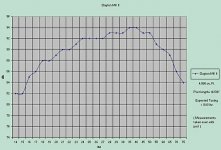
Port output should not be peaking around 40 Hz.
How long is your port? Yu mentioned 15 inches, I advised slightly longer. How long did you finally decide?
You might be running up against the limits of your SPL meter here with the high output. You need a low drive level for accuracy. Try this: Turn your amp level all the way down, so no power is going to the sub. Set your tone generator to 19 Hz. Put the meter directly in front of the port opening, flush with the front board. Slowly raise your amp level until the meter reads 90 dB. Then run the tones from 40 Hz down to 10 Hz. You should be peaking around 19 or 20 Hz-lower if you made the port longer than 15 inches.
The high power level might have caused your SPL meter to bump against it's physical limits. Let me know how it comes out.
" Is your enclosure the 142 litre Shiva with a Dayton in it??"
It is very close. The enclosure is a little smaller due to 2x4 blocking for attachment of the feet and top.
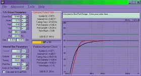
I just found the calculations I came up with for the true internal volume and it should be 4.89 cu. ft.
'"How long is your port?"
16 5/8" total including the flared ends (both ends).
I know , I wish I would have went longer.....
I used Box Port Design ver. 1.01.0002
It is very close. The enclosure is a little smaller due to 2x4 blocking for attachment of the feet and top.
I just found the calculations I came up with for the true internal volume and it should be 4.89 cu. ft.
'"How long is your port?"
16 5/8" total including the flared ends (both ends).
I know , I wish I would have went longer.....
I used Box Port Design ver. 1.01.0002
Attachments
The curve does not change with additional power. Only the volume goes up with additional power. The curve-the relative volume between different frequencies-will remain the same
Actually it changes quite a bit, try turning on the various non-linearities in Adire's free LSPCad, you'll see quite a big difference.
Port non-linearity also affects SPL.
Model a tempest in a 2cf vented box tuned to 25hz in WinISD and then compare it to what LSPCad tells you, pretty interesting
")
In fact, go into LSPCad and model the Shiva 2 for the same box, with non-linearities turn on, and you'll see a rather interesting SPL-curve. He's actually losing ~3-4db @ ~17hz due to port compression. There's also peaking in the mid 40hz region as well.
Also don't forget that the meter is not very accurate (but its better than nothing), and that those correction values are old.
As a general measuring distance for a sub, I'd say anywhere between 3-6ft for measuring it's actualy response should be fine.
Obviously measuring the port and driver would mean pointing the meter right at them.
Cj.9:
Well, I am a little stumped.
I do not have LSPCAD, so I cannot check Viperoni's plan.
Try this. The impedance of the speaker is at it's lowest at the tuning frequency. In fact, the impedance is often just 1 ohm above the DC resistance at the tuning frequency.
Do you have a multimeter that can measure AC current? If so, simply measure the current at any convenient drive voltage-amps send constant voltage-and measure from 50 Hz down to 10 Hz. The current should be highest at the tuning frequency, and it should be located in between two valleys where the current is lowest.
If you do not have a multimeter that can measure AC current, do you have one that can measure AC voltage? Just about all of them do.
If so, place a resistor of between 4 and 10 ohms in series with the speaker-NOT in parallel across it. One end of the resistor should be directly connected to the amp, the other end to the cable going to the speaker.
Place the probes of the multimeter across the RESISTOR. Run the test tones from 50 Hz down to 10 Hz.
At the places where the the voltage across the RESISTOR is greatest, the sub is experiencing an impedance trough. Both above and below the tuning frequency, the sub will experience the opposite phenomenon. The voltage across the resistor will drop at those frequencies.
Remember: When the voltage across the resistor rises, the sub is at LOW impedance, as it should at the tuning frequency.
When the votage across the resistor is low, the sub is having an impedance peak, as it should on either side of the tuning frequency.
Let me know how that comes out. The voltage across the resistor should be highest around 19 Hz or so.
Cj.9:
Assuming that works out OK, let me just give you a tip on how to measure the frequency response. Do you have a driveway with a paved or hard surface going up to a garage?
Put the sub against either the wall or the garage door. Put it so there is as much wall as possible on top and on either side of the sub. Step back six feet or so. Run the test tones and take your measurements.
If, after adjusting for the SPL meter, you find that the sub is close to 3 dB down from the midpoint around 20 Hz or so, then you have what you were going after.
What happens to it after you put it in a room remains to be seen. Room resonances, etc. change every sub's response. But at least you have a baseline to compare it to other subs. Moving the sub at various points in the room-which will certainly affect the bass output-is up to you.
Incidentally, after checking your picture, I just wanted to make sure-there is no stuffing around the interior opening of your port in the box, is there? Cannot tell that from the picture angle.
Let us know how this turns out!!
We must not forget, what sounds good, sounds good.
So what if your response isn't quite flat. There is a point where it's close enough.
Room placement will alter your frequency response to the point that anechoic [outside] response is almost irrelevant. Sit in the middle of the room and play your favorite song. Does is sound good?
Next, move the sub [or better yet, have someone move it for you] to a different location. Keep listening.
Find a good location, and now move yourself all around the room. The corners, find the standing wave patterns.
Experiment and see what placements work for you. I'm now thinking that you may limited, seeing that it doubles as an end table. Room placement
Cj.9:
Well, I think I might have an idea of why the port output looks like it does.
I have built several ported boxes, and they came out sounding just the way the equations predicted. I used a scientific calculator then-got a computer only a couple of years ago. Doesn't matter-the computer programs use the same equations I was using in my scientific calculator.
Mostly, I only did an impedance check to make sure that the box was tuned to where I expected-it always was.
Then, I did a measurement from 6 feet away with the speaker against a wall in a large room-the basement, actually-to check the response under close to anechoic conditions. If the mic is much closer than any corners, the response will be close to anechoic. The specs usually came pretty close.
I have also done a lot of reading. Universally, the articles show the port output as having a peak frequency, and 12 dB/octave slopes on both sides.
What I think I failed to realize was that those port curves were represented with a constant volume level coming from the speaker. In the real world situation, the relative output of the speaker cone gets less and less as it approaches the tuning frequency. The port action replaces the cone output as you approach tuning frequency. That is why the speaker as a whole has flat response down to the tuning frequency.
Take the sealed system. At 50 Hz, a 12 inch speaker must move .29 inches to produce an SPL of 112 dB, (@ 1 Meter). At 25 Hz, it must move 1.16 inches, (four times as far) to produce a tone at 112 dB.
In a ported system, the 12 inch must only move .29 inches or less at 25 Hz to produce a tone at 112 dB. In other words, at port resonance, the cone is only moving one quarter the distance that it needs to move in the sealed system. The port action is doing the rest.
Half an octave above the port frequency of 25 Hz-which is 35 Hz-the cone is moving half as much as it would in a sealed system.
So at the tuning frequency, the port action is strongest. At half an octave above, it is only half as strong. However, the cone output is stronger at half an octave above tuning frequency. So everything levels out.
The curves in the book where the port showed greatest output at the tuning frequency and 12 dB slopes above and below that were showing the strength of the port action-not the actual output of the port.
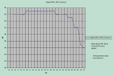
That is why you are showing a dropoff at 19 Hz-just where you expected it. Above 19 Hz, the port action dropoff is compensated by additional cone output the higher you go up the frequency scale. Below 19 Hz, the cone output does not compensate-so you see the port output go down from there.
Am I making any sense? No? Sorry.
All I can say is, take the sub outside or into a large room, put it against the wall, and measure the sound output from 6 feet away from 50 Hz down to 10 Hz at 1 watt or so. If the output is about 3 dB down at 19 Hz, consider the job done.
If it doesn't work out that way, come back. We'll think of something.
PS: Be very careful about sending high wattage tones to your sub below the tuning frequency. Below the tuning freuency, cone excursion in a vented box starts going out of control and the speaker soons starts exceeding it's safe travel distance. If your amp has a subsonic filter, use it. Don't send your sub 15 Hz tones at 50 watts!
Well, I think I might have an idea of why the port output looks like it does.
I have built several ported boxes, and they came out sounding just the way the equations predicted. I used a scientific calculator then-got a computer only a couple of years ago. Doesn't matter-the computer programs use the same equations I was using in my scientific calculator.
Mostly, I only did an impedance check to make sure that the box was tuned to where I expected-it always was.
Then, I did a measurement from 6 feet away with the speaker against a wall in a large room-the basement, actually-to check the response under close to anechoic conditions. If the mic is much closer than any corners, the response will be close to anechoic. The specs usually came pretty close.
I have also done a lot of reading. Universally, the articles show the port output as having a peak frequency, and 12 dB/octave slopes on both sides.
What I think I failed to realize was that those port curves were represented with a constant volume level coming from the speaker. In the real world situation, the relative output of the speaker cone gets less and less as it approaches the tuning frequency. The port action replaces the cone output as you approach tuning frequency. That is why the speaker as a whole has flat response down to the tuning frequency.
Take the sealed system. At 50 Hz, a 12 inch speaker must move .29 inches to produce an SPL of 112 dB, (@ 1 Meter). At 25 Hz, it must move 1.16 inches, (four times as far) to produce a tone at 112 dB.
In a ported system, the 12 inch must only move .29 inches or less at 25 Hz to produce a tone at 112 dB. In other words, at port resonance, the cone is only moving one quarter the distance that it needs to move in the sealed system. The port action is doing the rest.
Half an octave above the port frequency of 25 Hz-which is 35 Hz-the cone is moving half as much as it would in a sealed system.
So at the tuning frequency, the port action is strongest. At half an octave above, it is only half as strong. However, the cone output is stronger at half an octave above tuning frequency. So everything levels out.
The curves in the book where the port showed greatest output at the tuning frequency and 12 dB slopes above and below that were showing the strength of the port action-not the actual output of the port.
That is why you are showing a dropoff at 19 Hz-just where you expected it. Above 19 Hz, the port action dropoff is compensated by additional cone output the higher you go up the frequency scale. Below 19 Hz, the cone output does not compensate-so you see the port output go down from there.
Am I making any sense? No? Sorry.
All I can say is, take the sub outside or into a large room, put it against the wall, and measure the sound output from 6 feet away from 50 Hz down to 10 Hz at 1 watt or so. If the output is about 3 dB down at 19 Hz, consider the job done.
If it doesn't work out that way, come back. We'll think of something.
PS: Be very careful about sending high wattage tones to your sub below the tuning frequency. Below the tuning freuency, cone excursion in a vented box starts going out of control and the speaker soons starts exceeding it's safe travel distance. If your amp has a subsonic filter, use it. Don't send your sub 15 Hz tones at 50 watts!
You will always hear more low bass in a closed field than in an anechoic environment. For our purposes, I agree, it is close enough.
I have directions describing how to construct a subsonic frequency filter, which is a necessity with ported loudspeakers. Very simple and cheap. If you are not already covered I will gladly tell you.
-andy
I have directions describing how to construct a subsonic frequency filter, which is a necessity with ported loudspeakers. Very simple and cheap. If you are not already covered I will gladly tell you.
-andy
I have directions describing how to construct a subsonic frequency filter, which is a necessity with ported loudspeakers. Very simple and cheap
Please tell me too !
Keld
Ok, I have to now run upstairs.
I'm back. Note that I have not ever constructed one of these. Ok, here we go: subsonic filtering. Book says "vented enclosures are highly sensitive to subsonic information...excursion will greatly exceed xmax...large amounts of distortion...it is essential, therefore that you use either active or passive LF filtering with any vented loudspeaker."
An alternative to buying a filter is to build a simple passive CR filter
C1---C2-----
.....|....|
in...R1...R2..out
.....|....|
--------------
C1 - 0.47uf poly cap
R1 - 120K, 5% 1/2 W
C2 - 0.68uf poly cap
R2 - 100K, 5% 1/2 W
ignore all of the .... i couldn't get it to space correctly
This filter's f3 is dependent on the output impedance of your amp, which is 4ohms with the partsexpress amp.
-andy
In a similar vein, here is a page found on Planet 10's t-linespeakers page:
http://www.t-linespeakers.org/tech/filters/passiveHLxo.html
Good luck!
http://www.t-linespeakers.org/tech/filters/passiveHLxo.html
Good luck!
I thought I read that the Parts Express #300-794 amp had a rumble filter??
The only reference I can find now is on the "Adjusting EQ Bass Boost" Page for the amp.
Under step #2 ,C. , Last sentence.... "...The Fc is also an indication of the frequency where the rumble filter starts to take effect" Aren't they referring to a built in rumble filter????
Not sure if I mentioned earlier but I did change the resistors to eliminate the bass boost.
Chris
Cj.9:
I took a look at the spec sheet, the URL is given here for anyone who wants to look at it:
http://www.partsexpress.com/pdf/300-794.pdf
There are two resistors of importance: R26 and R27.
The lowest frequency bass boost is with R27 at 220,000 ohms. The lowest amplitude bass boost-1 dB-is with R26 at 56,000 ohms.
The lower R26 goes, the higher the bass boost. My initial reaction is to therefore increase R26 over 56,000 ohms to get a low bass blockage.
I don't have time to go into it this morning, but my suggestion for a rumble filter would be to keep R27 at 220,000 ohms and make R26 100,000 ohms or 150,000 ohms.
It sure would be nice if there was a tech to check this out with first, though. Maybe call Parts Express free tech help department. But that would be the way I would be thinking.
On the other hand, it's your money you are messing with, not mine, LOL. Call the tech help number and see what they say.
http://www.partsexpress.com/pe/pshowdetl.cfm?&DID=7&Partnumber=300-794
Quote from Page:
"250W SUBWOOFER AMPLIFIER
#300-794
List Price: $269.95 EA
Our Price: $128.00 EA
Special: $119.90 EA
QUANTITY:
--------------------------------------------------------------------------------
IN STOCK? Yes
CATALOG PAGE: 009
MFG/BRAND: Parts Express
See more Home Audio Products
High power Class AB amplifier
Variable phase adjustment
Rumble Filter
Gold plated connectors
High pass filter for satellite speakers
Auto On/Off "
Says it has rumble filter......
What do you think?
Cj.9:
Maybe the rumble filter is nonadjustable and not on/off-able, (is that a word)?
If you have a multimeter, then run test tones to the speaker from 25 Hz down to 10 Hz, and measure the voltage across the speaker terminals. If the voltage starts going down around 20 or 15 Hz, then you have a built in rumble filter.
- Status
- This old topic is closed. If you want to reopen this topic, contact a moderator using the "Report Post" button.
- Home
- Loudspeakers
- Multi-Way
- Sub Help