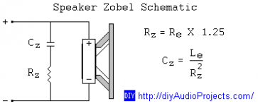
I've read on somewhere long time ago, the idea was presented that, by closely look at the imepedance equalization circuit, it is simply related to a 'low-pass' filter where Rz is the attenuation rate for the desired impedance and can be calculated by a simple formula: Rz = Re x 1.25 and Cz is the filter that is established at the starting point of the rising impedance. Unfortunately, I cannot remember the suggested method to calculate Cz from the frequency point where impedance starts to rise. By electrical circuit analysis, could anybody perform this to find the value of Cz without using formula involving Le, but using frequency point of rising impedance instead?
Attachments
Last edited:
You can load a .zma file of any driver to a simulator, add a Zobel network and arbitrarily adjust R and C until you get impedance that you find acceptable. Flat or not, depends what you wish to achieve with it.
XL=Re at the frequency where ZT=Re x √2
I couldn’t find Cz in the formula anymore. Could you please help to explain in detail?
From XL = Re, it might be equal to 2 x pi x f x L = Re. And what does Zt refer to? Thanks in advance
Last edited:
If I put it into words, when the inductive reactance equals the resistance, the impedance will be 1.4 times the resistance. This accounts for them being in series, and 90 degrees out of phase.
Note: that I'm not trying to calculate the impedance conjugate here.. I'm offering a way to get the inductance.
Note: that I'm not trying to calculate the impedance conjugate here.. I'm offering a way to get the inductance.
The problem is that the formula is nonsense and unfortunately it has found its way into technical papers and books; not to mention simulator programs.
To make a speaker behave as a resistor by using a compensating network requires finding the values of the voice coil resistance and inductance at a specific frequency, normally the desired crossover frequency. The impedance and phase graph of the speaker allows the resistance and inductance to be derived from,
Xl = sin theta Z. R = cos theta Z.
The solution requires finding the values of the compensating components ( R and C ) in the parallel network which is a Boucherot Cell. This requires vector analysis.
Indeed. RC is usually slightly imperfect anyway but within the tolerance of workability. Using a simple formula or working by sight on a simulator will get close.
Eg. R=Re x 1.25
and C=L/R2
Eg. R=Re x 1.25
and C=L/R2
Sorry AllenB, you are incorrect, that formula is nonsense. The reactive elements of C and L are Xl and Xc and these are frequency related; namely Xl=2PifL, Xc=1/2PiFC. Using maths enables the network to be calculated exactly, there is no need to fiddle with trial and error.
I don't disagree. (However some, like this one, include mechanical effects, eg the blip at 1400Hz.)
I decided to test the viability of the formulas in post #8. I picked a driver at random.
I've attached the *.zma file.
I decided to test the viability of the formulas in post #8. I picked a driver at random.
I've attached the *.zma file.
Attachments
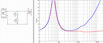
The problem with using maths in practice is that the thiele/small model is greatly simplified and you will find that the real world impedance deviates at high frequency from what the model predicts, as parasitics such as coil inter-winding capacitance and core losses become significant. At high freq the impedance no longer follows the R-L network that it did at low frequency, so therefore cannot be flattened by an R-C network over the entire frequency range.
It's much more effective to just do an impedance measurement and fudge the values of an R-C network to flatten the impedance as much as possible over a frequency range of interest - i.e. it's probably more important that a woofer impedance is flat from 200Hz to 5kHz than it is from 10kHz to 20kHz. You can add multiple R-C networks in parallel if you want to flatten it over a wider range of frequencies, but this is probably unnecessary in most cases.
In a lot of cases your impedance flattening network can perform double duties and help act as part of the low/high pass network - i.e. you can fudge the values so the impedance of the driver and network is no longer flat, in order to more closely hit the target response. Just watch that the impedance at the speaker terminals doesn't become too low at any frequency - it's easy to get carried away and make a filter that hits your target response exactly but falls to 1ohm or something low at ultrasonic frequencies which can make your amp unhappy.
Last edited:
If the driver is fed from a low impedance source like a typical amplifier, there is no direct relationship.
If the driver is used in a passive crossover, the impedance of the driver is important for the frequency
response, especially near the crossover points.
If the driver is used in a passive crossover, the impedance of the driver is important for the frequency
response, especially near the crossover points.
In simplified terms you have a driving Voltage, a load (the driver, and its impedance), and a source impedance (the crossover). The driving voltage passes a current through them which divides itself across them, so the crossover is reducing the voltage to the driver. This is called a voltage divider.
The higher an impedance, the more voltage is dropped across it. This suggest that with a driver impedance rise there will also be a relative increase in the drive signal it sees. However, you can arrange the crossover to expect that and work with it to provide any response you want.
The higher an impedance, the more voltage is dropped across it. This suggest that with a driver impedance rise there will also be a relative increase in the drive signal it sees. However, you can arrange the crossover to expect that and work with it to provide any response you want.
I’m now searching for the relationship between driver’s frequency response and its impedance behavior. Since I had observed that in some times, applying zobel/ impedance eq circuit not only led the impedance flatten but also smoothened the rising frequency response as shown on attached (Cr: A Speaker Maker's Journey: Crossover Basics - The Zobel). This might be implied that the zobel behaves as a low-pass filter. It’s interesting to study the relationship between low-pass filter properties and zobel’s; such as the cut-off frequency, the slope rate, etc.
Attachments
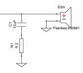
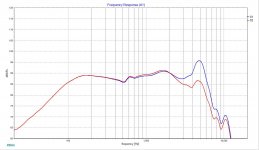
In reply to # 15 are you making the frequency response measurement or are you using a graph from another source? I ask as the Xsim is different from the Peerless one via other sources. A Zobel network is intended to adjust a speaker's impedance and phase response in the crossover region to allow the network to operate at its intended frequency . Since the Zobel in fitted in parallel, it does not have any appreciable effect on a speaker's frequency response as the voltage applied to the speaker remains the same; providing that the crossover is a conventional network like a Butterworth type.
Thankyou Lojzek, I only glanced at the referenced article in post # 16. So to be clear, the graph simply shows the effect of an impedance correcting network applied to a speaker with a crossover filter.
Yes. It's how the driver impedance and the crossover impedance work together as a circuit. If we showed an example of getting the same response with and without the Zobel, it would demonstrate how the relationship is a two way street.relationship
In the reference blog, ''A Speaker Maker's Journey....'' a brief mention of Dr Marshall Leach is made and some of his papers reveal how the inductance and resistance of a voice coil vary with frequency due to losses. This knowledge is important in the design of an impedance correction network and why it should co-incide with the chosen xover frequency if it is to work as intended.
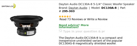
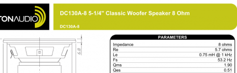
I looked up the manufacturer's data for the Dayton DC130A-8 Bass/ Mid speaker and looked at the graphs and T & S Parameters but I was unable to download the zma file as my computer considers that it is corrupted. I had no problem with the file provided by AllenB.
I performed some calculations from that zma file and found that at 1 kHz * the Le is 0.422mH ( not the listed 0.745 mH value ) and Re to be 6.89 ohm. To make this speaker appear as a resistive load 7.5 ohm ( 0 degrees phase angle) requires a correction network consisting of a 20 ohm resistor and a capacitor of 57 mfd. 1 kHz is an unlikely point for a crossover for this particular speaker and a 3 kHz * frequency is a more likely proposition. Calculating from the zma file gave the new Le as 0.34283 mH and Re as 9.141 ohm. The correction network to make the DC 130A speaker appear as a 7.5 ohm load consists of a 9.6 ohm resistor with a 6.493 mfd capacitor.
*994.849 Hz.
2981.178 Hz.
Last edited:
- Home
- Loudspeakers
- Multi-Way
- Applying Impedance Equalization Circuit without knowing voice coil inductance