I am making a pair of small 2 way speakers for my basement workshop. I would like some feedback on my crossover design. It has been 18 years since I designed a passive crossover, and a lot of measurement and simulation technology has changed in that time. Best Practices have changed as well. So I am asking for opinions, thoughts, and advice before I order the parts for the passive crossovers.
Background
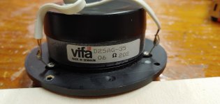
I am reusing the Vifa D25AG35 tweeters I pulled from my old speakers. Although they are 28 years old and have seen almost daily use, these tweeters still have the same frequency response and impedance curve as when they were new. Harmonic distortion is very good even by today’s standards.
These tweeters always worked so well with a polymer cone driver (Vifa P13WH in the old speakers). My basement can experience big seasonal changes in humidity, so I wanted to stick with poly cone drivers. I have had good experience with SB Acoustics SB17 series drivers, so I chose the SB17MFC35-8. This will be a sealed box system.
These speakers will be located on a large 8 ft x 3 ft work bench, with the speakers pushed back against a concrete wall. So they will be at the corner interface of a vertical concrete wall and a large flat wood surface. I am assuming I will need little to no baffle step correction, and this is confirmed by plots of total room response compared to ground plane response.
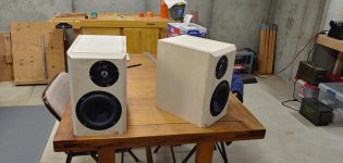
The box is 12.6 liter internal volume, not accounting for the volume of bracing and driver magnets. External dimensions are 13.5 inches tall, 8.25 inches wide, 11.75 inches deep. Internal dimensions are 12 inches tall, 6.75 inches wide, 9.5 inches deep. Wall thickness is 0.75 inch, baffle thickness is 1.5 inch. The sides and top edge have been beveled with a 45 degree angle to a depth of 0.75 inch. I do not plan to apply a finish to these speakers at this time.
Another reason for this project is I wanted to explore various ideas for constructing cabinets more efficiently. Some of those ideas worked out well, others not so much…
Background
I am reusing the Vifa D25AG35 tweeters I pulled from my old speakers. Although they are 28 years old and have seen almost daily use, these tweeters still have the same frequency response and impedance curve as when they were new. Harmonic distortion is very good even by today’s standards.
These tweeters always worked so well with a polymer cone driver (Vifa P13WH in the old speakers). My basement can experience big seasonal changes in humidity, so I wanted to stick with poly cone drivers. I have had good experience with SB Acoustics SB17 series drivers, so I chose the SB17MFC35-8. This will be a sealed box system.
These speakers will be located on a large 8 ft x 3 ft work bench, with the speakers pushed back against a concrete wall. So they will be at the corner interface of a vertical concrete wall and a large flat wood surface. I am assuming I will need little to no baffle step correction, and this is confirmed by plots of total room response compared to ground plane response.
The box is 12.6 liter internal volume, not accounting for the volume of bracing and driver magnets. External dimensions are 13.5 inches tall, 8.25 inches wide, 11.75 inches deep. Internal dimensions are 12 inches tall, 6.75 inches wide, 9.5 inches deep. Wall thickness is 0.75 inch, baffle thickness is 1.5 inch. The sides and top edge have been beveled with a 45 degree angle to a depth of 0.75 inch. I do not plan to apply a finish to these speakers at this time.
Another reason for this project is I wanted to explore various ideas for constructing cabinets more efficiently. Some of those ideas worked out well, others not so much…
Attachments

Measurements
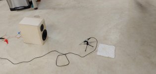
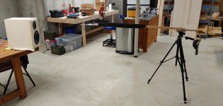
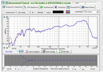
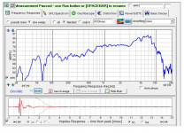
I included photos of my measurement setup for gated response and for ground plane response. The input drive voltage was approximately 1 V. Measurements were taken on the tweeter axis at a distance of 22 inches, 40 inches from the floor.
The Vifa tweeter gated response is used as-is.
The SB17MFC woofer response was spliced to the ground plane response at 300 Hz.
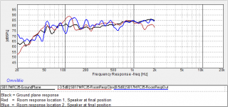
To verify that I do not need a baffle step correction, I put the speaker in its final position, with its back up against the concrete wall, sitting on a wide, deep table. I took two room response measurements, one from the standpoint of a person seated at the table, and another 8 feet out into the middle of the room. I put all three curves on the same plot (2kHz and below). You can see that the real-world in-room response is about 3 dB higher than the ground plane response in the region from 100 Hz to 300 Hz. From this I conclude I do not need a baffle step correction.
I included photos of my measurement setup for gated response and for ground plane response. The input drive voltage was approximately 1 V. Measurements were taken on the tweeter axis at a distance of 22 inches, 40 inches from the floor.
The Vifa tweeter gated response is used as-is.
The SB17MFC woofer response was spliced to the ground plane response at 300 Hz.
To verify that I do not need a baffle step correction, I put the speaker in its final position, with its back up against the concrete wall, sitting on a wide, deep table. I took two room response measurements, one from the standpoint of a person seated at the table, and another 8 feet out into the middle of the room. I put all three curves on the same plot (2kHz and below). You can see that the real-world in-room response is about 3 dB higher than the ground plane response in the region from 100 Hz to 300 Hz. From this I conclude I do not need a baffle step correction.
Attachments

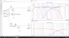
Crossover design
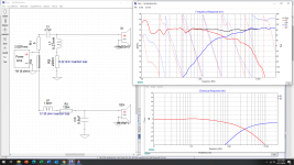
I tried 1st order and 2nd order topologies on the woofer. I tried 2nd order and 3rd order topologies on the tweeter. Here is the best I have come up with so far.
I have included the insertion loss of the inductors as a small resistor in-line.
The woofer *.frd file has ground plane response below 300 Hz. As I said above, I think the real world response will be ~ 3dB higher than this in the 100 - 300 Hz range.
I welcome any thoughts on my assumptions, my measurement techniques, or my attempt at crossover design… Thanks !!!
Attachments
Last edited:

Where is the L-pad? How are you going to adjust the tweeter loudness? DSP? Or the norm for this forum: after a few days it will sound just right if you are anywhere near a reasonable FR.
B.
B.
Thanks for the feedback, Ben...
In the past I have used driver-side L-pads, but I noticed many designs use an amp-side series resistor instead, so I tried it. According to my Xsim simulations... I can vary the tweeter resistor from 2 ohm to 10 ohm without changing the crossover characteristics. This would give me several dB of play in the tweeter response.
Am I missing something?
Jim
Nice work, looking good.
This is very similar to most mini monitor crossovers with baffle step compensation.
What you have is (very) roughly 4th order electro acoustic, 2nd from the XO and
another 2nd from the drivers. The drivers should be in phase at the crossover point.
So, if you invert one of the drivers you should get a notch at XO.
Right click on the tweeter and select invert to try this.
Then, tune the tweeter cap and you'll end up with a XO point a bit over 2 KHz.
You might try a few more dB of attenuation on the tweeter and a bit more baffle
step by making the inductor 2.2 or 2.5 mH. A bit of droop at the crossover point can
sound very good which you can try by increasing the woofer cap.
Enjoy the tuning process, you're very close.
One thing I did not check is the acoustical offset, if your measurements are off
then the optimum axis will be tilted.
then the optimum axis will be tilted.
You say that you do not have or need baffle step, but if you go to the AddGraph-More-FilterResponse
and select S2 to plot, notice that from 100 Hz to 1KHz the response rolls off by 5dB. Seems you
have about 5dB.
The clue that you _do_ have baffle step is that the woofer inductor is rather large. Reduce
it and you'll see that for no baffle step the value is below 1 mH. I find that 3 dB of baffle
step is about right against the wall, but also on a table might be different. 1.2 mH gets
you about 3 dB. If you change the inductor you should retune the cap to obtain the XO
point you want. You want the woofer total output to be -6dB re 1KHz at the XO point
since they are summing in phase. Also, retune the tweeter network as needed for the
reverse null. Note also that the XO is compensating for any rise in the woofer's response
that you should keep in mind.
Last edited:
Thank you for the comments Pete.
You are right of course that my current design does include some baffle step correction. My thought process was that I did not need any additional baffle step, since the speakers get an additional 3 db of gain in the 100 - 300 Hz range by being located on the table against the wall. In other words, an additional 3 dB that is not reflected in the current FRD file.
Here I show the result if I splice the room response instead of the ground plane response. However, I am not sure if this kind of splice is technically valid... I have never seen it done. Most people use the near field or ground plane response.
Be that as it may, I am going to try your suggestion for a little more beef in the woofer inductor, followed by a rebalancing everywhere else.
Attachments
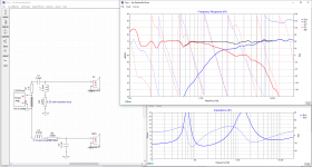
Here is Rev A, based on Pete's feedback.
Below 600 Hz, there are two curves... the lower one is the original FRD file based on splicing the ground plane response to the gated response at 300 Hz.
The upper curve is based on an alternate FRD file: splicing the room response to the gated response. I am still not sure this is correct... intuitively is seems right.
The reverse null is now deeper than it was, and the phase match between the drivers is better (naturally).
I updated the zip file to include both of the woofer FRD files. The new one is "SB17MFC35-Spliced-2.frd"
Attachments

My initial suggestion was to provide more baffle step that is usually required for
speakers out in the room.
If you want less then use my second suggestion for a woofer inductor of 1.2 mH.
You might want to listen and compare the two as a learning experience. You can do
just one speaker in mono to get an idea of the effects.
speakers out in the room.
If you want less then use my second suggestion for a woofer inductor of 1.2 mH.
You might want to listen and compare the two as a learning experience. You can do
just one speaker in mono to get an idea of the effects.
Almost touching on your own question here, a reason it is usually referred to as compensation, rather than correction is that the change in directivity is something the crossover cannot change. The room interaction changes also. As you can see, the response with and without the room has features that make them different.baffle step correction.
...
the room response
...
if this kind of splice is technically valid
Nicely done, but I wonder if 12.6L is a bit small for closed box here, especially with a reflex driver?
Another way to do the bass filter, aside from the usual 1.5mH/6.8uF idea is to use a LCR notch around 4-6kHz with a simple coil around 1.5mH. Quite a good idea where there is some breakup.
SBAcoustics-61-MFC
SB17MFC358 x2 + D26069220 Passive Crossover Design - Madisound Speaker PDF Library
Might be 3.3uF/0.3mH and 2.2R. See how it looks. 🙂
Just thinking of a sidestep. With small enclosures like this one, the BSC using a big inductor more often than not leads to too much damping in the 500Hz-1kHz octave. That doesn't always show up in measurements these days, because of the small time windows we use.
Back in the nineties, doing small speakers like this in an anechoic room, I often ended up using tuned LCR circuits to compensate for the quick rising baffle step of small speakers.
Back in the nineties, doing small speakers like this in an anechoic room, I often ended up using tuned LCR circuits to compensate for the quick rising baffle step of small speakers.
Final Results
I thought I would close out this thread and show the final results.
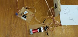
The first image is the final crossover configuration as built. The second images is the crossover construction.
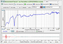
I gave it a listen, and it seemed overly bright. I measured it, and confirmed my suspicions. The next image is the measured frequency response, using the same test setup as shown in post #2.
I thought I would close out this thread and show the final results.
The first image is the final crossover configuration as built. The second images is the crossover construction.
I gave it a listen, and it seemed overly bright. I measured it, and confirmed my suspicions. The next image is the measured frequency response, using the same test setup as shown in post #2.
Attachments
If it sounds too bright then it is too bright.
Measurements are crucial but only represent a correlation to the audible experience, not a meaningful standard (such as perceptually "flat"). The room factors that lead to sounding right aren't the same factors that lead to measuring right.
So at your stage, the key is to keep your measurement system absolutely stable and make changes to EQ iteratively, working to your ear not to the plot. You need the successive plots to see what you are effecting as you spin the DSP dials. After - with the help of DSP testing - you can hardwire your crossover to match the sound you like.
BTW, doesn't the direction the mic is pointing matter? Isn't the direction in the first photo in post 2 the wrong orientation by 90 degrees?
B.
Last edited:
- Home
- Loudspeakers
- Multi-Way
- Request Peer review of crossover