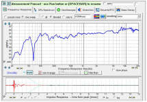
I re-measured the drivers, and found that I had made a mistake somewhere. Either the tweeter was 3 dB more sensitive than I originally measured, or the woofer was 3 dB less sensitive. A likely culprit was the splice between the woofer ground plane response and gated response... I probably erred in that process. In any case, I had a problem, and the cause was not important... fixing it was. The measured response is shown in the first image.
The crossovers were glued in place, so my surgery options were limited. I did some more work in Xsim, and decided the easiest way to fix this was to add some amp-side resistance to the tweeter. An additional 4.7 Ohm seemed to make things right.
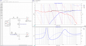
Shown is the retrofit crossover, with the tweeter response corrected to its true sensitivity relative to the woofer.
The crossovers were glued in place, so my surgery options were limited. I did some more work in Xsim, and decided the easiest way to fix this was to add some amp-side resistance to the tweeter. An additional 4.7 Ohm seemed to make things right.
Shown is the retrofit crossover, with the tweeter response corrected to its true sensitivity relative to the woofer.
Attachments
So now I had to wait a week for a pair of 4.7 Ohm resistors... as well as paying shipping costs that were 5x the price of the resistors alone.
I was able to use the speakers in the mean time... the old reciever has tone controls, and this tamed the hot and spicy tweeter enough to make it listenable.
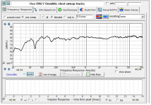
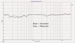
With the new resistors in place, the sound was much improved. The first image is the measured response of the retrofit crossover. The second image compares the Xsim simulation with the actual measured response. This retrofit response is very similar to the original goal.
I am quite pleased with how they sound. They do not sound as nice as my active 3 ways, but my cost for these little workshop speakers was less than 10% of the cost of my main system. I think I have about $200 in them.
I was able to use the speakers in the mean time... the old reciever has tone controls, and this tamed the hot and spicy tweeter enough to make it listenable.
With the new resistors in place, the sound was much improved. The first image is the measured response of the retrofit crossover. The second image compares the Xsim simulation with the actual measured response. This retrofit response is very similar to the original goal.
I am quite pleased with how they sound. They do not sound as nice as my active 3 ways, but my cost for these little workshop speakers was less than 10% of the cost of my main system. I think I have about $200 in them.
Attachments
Last edited:
Appreciate that mtidge... My goal in this project was to get some good sound down in my workshop, but also to explore some labor saving cabinet construction techniques. I also wanted to do a passive crossover with modern tools... the last time I did one was 18 years ago. I intended this to be a learning experience, so its all good...
Good effort hifijim! TBH, you might as well get a batch of resistors to allow adjustments. At $1 a pop it doesn't hurt much. 😀
I had to do a lot of attenuation on my Mordaunt Short MS10 "upgrade" project:
Mordaunt Short MS10
TBH, closed box bass was always lacking. But interesting. There's nothing like actually doing it.
I run into the same problem, I need a $5.00 of parts from Parts Express and end up buying $50.00 or more to get free shipping and a coupon. Madison Sound is even more expensive. To bad we didn't have a simple way of sharing parts on the forum.
TBH, you might as well get a batch of resistors to allow adjustments. At $1 a pop it doesn't hurt much.
Oh yes. I just recently gave this advice to someone else on this forum (stemming from my very recent experience)...
Shipping costs for small items are a painful factor in many areas of life. I once needed a small gasket to repair an electric generator on my boat, and I needed it for the start of vacation. The gasket was $12. Overnight FedEx was $40. But I got it repaired and had a nice vacation, so there ya go ...
Having knocked around this game for a few years, you start to notice what works well:
John DeVore is a clever bloke IMO. This is the 6" plus 3/4" driver 32L reflex Gibbon 88. Can't quite remember the details, but this speaker went for serious bucks.
Test Report: DeVore Fidelity Gibbon 88 Tower Speaker | Sound & Vision
2 way 6" bass is quite hard to do well, IMO. But there's always a Mk.II, right?
Last edited:
The first image is the measured response of the retrofit crossover. The second image compares the Xsim simulation with the actual measured response. T
I am puzzled. Is that black curve something that came from a simulation or from a mic? Seems too granular to be from a simulation. Pretty good match north of 300 Hz.
B.
Minor note -unless I'm missing something (probable, not having slept for a couple of nights) you've added resistors to represent the resistance of the inductors in XSim, correct? But the XSim files already consistently appear to be including its default 0.35ohm for each inductor, so if that's the case, the sim is including more resistance than you may have accounted for in these elements / poles.
I am puzzled. Is that black curve something that came from a simulation or from a mic? Seems too granular to be from a simulation. Pretty good match north of 300 Hz.
The black is the Xsim simulation of the retrofit crossover (with the correct tweeter FRD curve and the additional 4.7 Ohm).
The gray curve is the FRD curve from the whole system.
Omnimic software does this "blending" process where the gated quasi-anechoic response is blended into the room response begining at the time window of your choosing - for my test setup it is about 4 ms. There is not a lot of documetation about how the blend works, but I have to admit it works pretty well. I have done my own splicing of near field and/or ground plane curves onto the gated quasi-anechoic, and it is not that much different than just using the Omnimic blend... except for the expected floor and cieling cancellation.
So that may be a reason why the match is so good in the lower frequencies: The whole system FRD curve and the woofer FRD curve were both based on the blended room response.
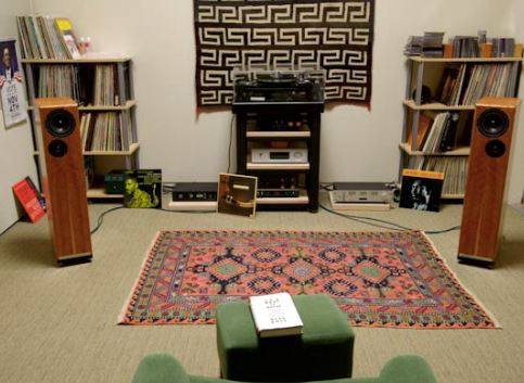
Earlier you asked about the photo of my test setup. I am not sure if the photo is clear: The mic is pointed at the tweeter, on the axis of the tweeter, at a distance of 22 inches. Make sense?
Last edited:
Scottmoose wrote
Yep, missed that one didn't I. I just checked my Xsim file, and the difference it makes is less than the thickness of the line... so I got lucky.
Minor note -unless I'm missing something (probable, not having slept for a couple of nights) you've added resistors to represent the resistance of the inductors in XSim, correct? But the XSim files already consistently appear to be including its default 0.35ohm for each inductor, so if that's the case, the sim is including more resistance than you may have accounted for in these elements / poles.
Yep, missed that one didn't I. I just checked my Xsim file, and the difference it makes is less than the thickness of the line... so I got lucky.
My poor grasp of mics is that your mic's calibration and operation says it should be at right angles to the speaker, not pointing to it. Can others please speak up here...Earlier you asked about the photo of my test setup. I am not sure if the photo is clear: The mic is pointed at the tweeter, on the axis of the tweeter, at a distance of 22 inches. Make sense?
B.
..Omnimic software does this "blending" process where the gated quasi-anechoic response is blended into the room response begining at the time window of your choosing - for my test setup it is about 4 ms. There is not a lot of documetation about how the blend works, but I have to admit it works pretty well. I have done my own splicing of near field and/or ground plane curves onto the gated quasi-anechoic, and it is not that much different than just using the Omnimic blend... except for the expected floor and cieling cancellation.
So you take a mic plot of the tweeter, add the influence of the crossover (which happens to be zero north of the XO region) and then replot it. If I have that right, then you need to explain why the two curves aren't identical (not why they are similar).
As always, a matter of great faith to make a crossover without an L-pad for the tweeter, eh.
B.
My poor grasp of mics is that your mic's calibration and operation says it should be at right angles to the speaker, not pointing to it. Can others please speak up here.
B.
My UMIK 1 came with an on axis calibration file and a 90 degree file. I don't know about other mics. I only use the 90 degree calibration file for room measurements at listening position.
So you take a mic plot of the tweeter, add the influence of the crossover (which happens to be zero north of the XO region) and then replot it. If I have that right, then you need to explain why the two curves aren't identical (not why they are similar).
I would never expect the two curves to be identical. A small movement of the microphone by a few cm up or down, right or left could easilly produce a dB or so of variation.
Even with a crossover at 2k, the woofer contributes to the output all the way up to 6 k.
The simulation matches reality to the extent that matters. it is "good enough".
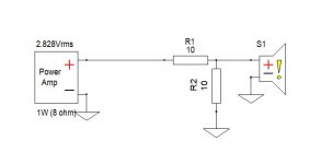
When you talk about a tweeter L-pad, do you mean a resistor network like the attached image, where R1 and R2 and chosen so as to attenuate the driver without changing the apparent impedance of the driver? Or are you talking about one of those potentiometer thingys which allow you to vary the level of a driver by twisting a knob?
Attachments
You've already touched on various ways it can be done. (By the way, a variable L-pad is slightly different to a potentiometer.)
Different ways have different advantages. An L-pad near the driver is often used because it offers reduced interaction, for itself and for the crossover before it, to driver impedance variations. (There is nothing wrong with these variations, only this style tends to simplify design and is easier to work with making it popular.)
The version you used above, where the resistor is before the filter, is perfectly acceptable if it does the job.. It happens to be similar to the style used in the Without Measurements sticky, so I'll just add that I found that to be a safer choice when tweaking by ear. It was all about reducing tweeter level without accidentally causing peaking in the resonant circuit, but when you are simulating there is no such concern.
The pre (before) amplifier version takes advantage of a Voltage interface for minimal downside. It's possible to just throw in a potentiometer but ideally the source and load are looked at and in some cases slightly modified.
It is an interesting subject, Allen. I went back and re-read the section in the "Loudspeaker Design Cookbook" and confirmed what Vance was saying.
When I was doing this 20+ years ago, I always put a resistor network between the filter and the driver, and carefully tailored it to maintain the driver impedance, or at least maintain the DC resistance. Now with cheap powerful simulations, we have more options.
I can certainly see the attraction of a variable L-pad. It would have saved me some work.
- Home
- Loudspeakers
- Multi-Way
- Request Peer review of crossover