I have a pair of woofer and its crossover networks. I obtained a pair of the same. I’d like to make the dual-woofer system. So, I put a pair of them in a cabinet. Since the driver resistance is low, approx. 3.6 ohms each, I wired them in series connection. The impedance now is about twice of the original, says 7.2 ohms. The original crossover is simply a 2nd order. So thing I have to do is to double the value of an inductor and a capacitor? Is it right? Thank you in advance
What if I half the impedance by placing a resistor with the same value as the driver, says 3.6 ohms, parallel to those series woofers? I know that it will be a heat loss on a parallel resistor but the placement is the nearest to the driver and behind all crossover components. An L-Pad circuit might be the same way. What do you think?
Last edited:
If you supply details of your woofers and crossover networks then I may be able to give you more targeted advice."I have a pair of woofer and its crossover networks."
I would certainly never use resistors to alter impedance in the way you suggest. The large loss of power and the need for very high power rating resistors to dissipate that power as heat would not be acceptable.
The woofers and crossover networks are from ADS L990 speakers. The woofer DC resistance is 3.6 ohms. Crossover network is 2nd order consisting of a 68 uF capacitor and a 3 mH inductor. Please note that this combination is for a single woofer.
For power rating of resistors, I’ve seen the resistors in midrange and tweeter sections. They are placed at the beginning of the path, series connecting direct to the speaker terminal. They are rated at 7W. I’m not sure if it will work for a parallel placement nearest to the drivers?
For power rating of resistors, I’ve seen the resistors in midrange and tweeter sections. They are placed at the beginning of the path, series connecting direct to the speaker terminal. They are rated at 7W. I’m not sure if it will work for a parallel placement nearest to the drivers?
Last edited:
To cross over a series pair of your woofers at the same frequency as one requires the following values of C and L:
C = 34µF and L = 6mH
If you have four of the original crossover boards then you can obtain the above values as follows:
Place two 68µF capacitors in series and you have a 34µF capacitor.
Place two 3mH inductors in series and you have a 6mH inductor.
You would then place the 34µF capacitor in parallel with the series woofer combination and the 6mH inductor in series with that combination.
P.S. Whatever you do, do not put resistors in parallel with your woofers to make them look like half the impedance!
Galu, could you please explain why resistor in series on the amp side is acceptable? For the parallel case, I think I might know the reason, the resistor with same value as woofer may consume current as same amount as the drivers or something like this.
Yes, a large fraction of the power from your amplifier would be converted into heat instead of into sound. The resistors would get very hot whereas the woofers would radiate the majority of the energy away as sound and remain (relatively) cool.For the parallel case, I think I might know the reason, the resistor with same value as woofer may consume current as same amount as the drivers or something like this.
In addition, woofers do not behave like pure resistors. Their impedance varies with frequency while the parallel resistors would maintain a constant value of resistance. How that would mess up the bass response I cannot imagine!
Now, you ask why a resistor in series is acceptable. My answer is that a resistor is acceptable when placed in series with a midrange or treble speaker in order to provide attenuation, but only because the power going to a midrange of treble speaker is a small fraction of the total system power.
Most of the power is in the bass frequencies so putting a resistor in series with a woofer would result in a very hot resistor and an unwanted waste of bass power.
In speaker design, the Woofer is chosen to be less sensitive that the mid and/or tweeter. This obviates the need to attenuate the woofer and allows fine adjustment of the mid and treble levels through the use of attenuating resistors.
As you can see on attached, there are 2.7 and 6.8 ohms resistors on tweeter and midrange circuit for attenuation. They are connected directly to the speaker terminal which also connect to the amplifier. Do the components below them help alleviate the dissipating?
Attachments
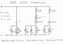
The components below the resistors are the crossover components which provide a low pass filter on the woofer, a band pass filter on the mid and a high pass filter on the tweeter.
Check your drawing. The top of the '18' capacitor in the mid's section should go to the junction of the '.60' and the '12.2' and not to the top of the '2.6'.
Check your drawing. The top of the '18' capacitor in the mid's section should go to the junction of the '.60' and the '12.2' and not to the top of the '2.6'.
Galu, could you please explain why resistor in series on the amp side is acceptable? For the parallel case, I think I might know the reason, the resistor with same value as woofer may consume current as same amount as the drivers or something like this.
MOST of the music "energy" is at 500 Hz or below. It takes a LOT more power the lower you go in frequency. Midrange and tweeter drivers "see" only a very small fraction of the total power; woofers "see" the greatest majority of the amplifier power. There are papers on this if you want to do more searching and reading. The only time you would use a resistor in a woofer circuit would be a Zobel for (upper frequency) impedance compensation. Resistors should be avoided in woofer circuits as either series to attenuate or parallel as an attempt to alter the impedance. (The Zobel circuit is affecting mostly the higher impedances at the higher frequencies due to rising VC inductance, etc. and does NOT "rob" power or get hot at the lower frequencies because of the capacitor [ie RC circuit vs resistance only]).
- Home
- Loudspeakers
- Multi-Way
- Doubling crossover’s value