I have been thinking for a while about a small and "simple" synergy horn design and I came up with the following.
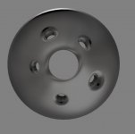
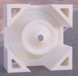
A 3D printed waveguide/phaseplug/reflex port device that fits in a 12" by 12" by 9" ply box.
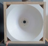
The design process started with making a waveguide that sits on the HF exit of the BMS 6.5" Coax and naturally extends its flare.
The HF exit has a kind of an exponential metal flare where the very bottom of the throat has a diameter of about 1cm and mouth has a diameter of 3cm.

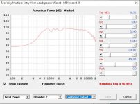
In Hornresp (Thanks for the great tool David!) I split the horn in 4 segments - the first being the HF exit of the BMS and the mid tap being between the 2nd and 3rd segment, so that I can play around with the distance from the throat of the horn.
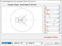
Having in mind that I should keep the taps 1/4 wavelength (the BMS has a 1300Hz recommended crossover) I placed the taps 6cm from the horn throat.
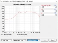
After playing around with the length/area of the segments while trying to keep it under 12" in diameter I came up with the following design..
In order to extend the LF I decided to let the back side of the paper membrane be open to the rest of the ported box.
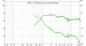
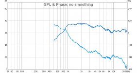
The REW measurement consists of the raw response of both HF and LF, with a 12db LR HP filter at 1200Hz on the HF. The taps/ports act like a natural bandpass/lowpass so I decided not to lowpass the LF.
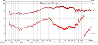
The setup is bi-amped running through a dsp with FIR filters and with a bit of messing around I flattened the magnitude response as well as the phase to a certain degree.

It's a pretty nice sounding speaker!
Now the issues:
1) There are 2 nasty high Q dips at 6340hz and 7800hz.
I tried covering the midrange taps with tape and measuring and yes, the dips are caused by the taps...
2) When playing at high level the midrange taps reach critical air velocity and start distorting... I was kind of aware that it will happen 😀
Has anybody tried a similar design?
Or successfully managed to hide their midrange taps at such a high crossover frequency?
The current design is conical with one expansion flare at the horn mouth.
Any clever horn types that could be more suitable for the purpose?
I don't find much information about horns with rapid expansion...
Most of the information I stumble upon is horns that are very long compared to their throat circumference...
Let me know what you think!
Stan
A 3D printed waveguide/phaseplug/reflex port device that fits in a 12" by 12" by 9" ply box.

The design process started with making a waveguide that sits on the HF exit of the BMS 6.5" Coax and naturally extends its flare.
The HF exit has a kind of an exponential metal flare where the very bottom of the throat has a diameter of about 1cm and mouth has a diameter of 3cm.


In Hornresp (Thanks for the great tool David!) I split the horn in 4 segments - the first being the HF exit of the BMS and the mid tap being between the 2nd and 3rd segment, so that I can play around with the distance from the throat of the horn.

Having in mind that I should keep the taps 1/4 wavelength (the BMS has a 1300Hz recommended crossover) I placed the taps 6cm from the horn throat.

After playing around with the length/area of the segments while trying to keep it under 12" in diameter I came up with the following design..
In order to extend the LF I decided to let the back side of the paper membrane be open to the rest of the ported box.

The REW measurement consists of the raw response of both HF and LF, with a 12db LR HP filter at 1200Hz on the HF. The taps/ports act like a natural bandpass/lowpass so I decided not to lowpass the LF.

The setup is bi-amped running through a dsp with FIR filters and with a bit of messing around I flattened the magnitude response as well as the phase to a certain degree.

It's a pretty nice sounding speaker!
Now the issues:
1) There are 2 nasty high Q dips at 6340hz and 7800hz.
I tried covering the midrange taps with tape and measuring and yes, the dips are caused by the taps...
2) When playing at high level the midrange taps reach critical air velocity and start distorting... I was kind of aware that it will happen 😀
Has anybody tried a similar design?
Or successfully managed to hide their midrange taps at such a high crossover frequency?
The current design is conical with one expansion flare at the horn mouth.
Any clever horn types that could be more suitable for the purpose?
I don't find much information about horns with rapid expansion...
Most of the information I stumble upon is horns that are very long compared to their throat circumference...
Let me know what you think!
Stan
Last edited:
Very cool, been working on a similar idea myself, but without the coax driver (just using a small 3/4 driver in the middle.
I think you can try taking some inspiration from JBL, by doing 'blended' diffraction. add more holes (to lower distortion) but move them so they are all different distances from the center. this will smear the diffraction more. you should probably flair the ports too.
look in the ATH4 thread, you will see that adding a large roundover will make the horn sound much better, adding this is probably a good idea as well
I have a long term project of the same nature. Uses a Vifa ne265 with the dome cut out of the cone and an Aurasound ns2 in the voicecoil. The wave guide is fabricated from fabric stretched over a mount and resin.
Very nice work - super clean 3D print. I think Danley has a patent and a commercial speaker that uses the same method of coaxial for the midrange. I would not worry so much about a high Q dip. Our ears don’t hear dips, especially high Q ones. We hear peaks which are much worse in terms of problems they add to sound. Try making the mid injection ports larger (up to 15% of Sd) and extend them length wise a bit to smear out the sharpness. Also put them a bit different distances from throat attack mentioned earlier. You want to keep velocity in port below 15m/s to avoid chuffing and turbulent flow effects.
Thanks for the tips!
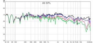
Here's a measurement at different angles:
Black - On Axis
Blue - 15 degrees off
Red - 30 degrees off
Green - 45 degrees off
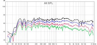
The degree of rotation is approximate, as I just turned the speaker (didn't make a turntable for measurements yet)
The dips appear and disappear..
I'm working on the horn shape atm..
This is my work drawing, It's just half of a crossection that I wrap around to make the shape, since it's concentric.
The blue selection is the actual horn shape.
The dot at the base is where the inbuilt waveguide starts and expands in an exponential fashion from Ø1cm to Ø3cm where it connects to the horn.
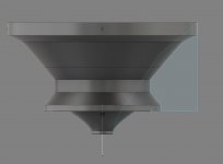
There are certain things that are problematic:
1) There is a very tight space for the connection between the inbuilt waveguide and the horn mouth, as the paper cone needs to be able to move "up and down"
2) It's hard to optimise for low chamber volume while keeping the midrange taps short in length.
Here's a measurement at different angles:
Black - On Axis
Blue - 15 degrees off
Red - 30 degrees off
Green - 45 degrees off

The degree of rotation is approximate, as I just turned the speaker (didn't make a turntable for measurements yet)
The dips appear and disappear..
I'm working on the horn shape atm..
This is my work drawing, It's just half of a crossection that I wrap around to make the shape, since it's concentric.
The blue selection is the actual horn shape.
The dot at the base is where the inbuilt waveguide starts and expands in an exponential fashion from Ø1cm to Ø3cm where it connects to the horn.

There are certain things that are problematic:
1) There is a very tight space for the connection between the inbuilt waveguide and the horn mouth, as the paper cone needs to be able to move "up and down"
2) It's hard to optimise for low chamber volume while keeping the midrange taps short in length.
Nice speaker! Have you checked the greatest horn thread in human history?😀 Acoustic Horn Design – The Easy Way (Ath4) there is kind of a conclusion from lots of simulations that smooth horn mouth solves lots of issues with horns. There is a script that will give you STL file for the design you do and ABEC project to simulate that (no midrange taps though). You can design to constraints like 12" mouth size, depth, desired coverage etc 😉
I actually do have Ath4 and It's an amazing tool!
I have experimented with various parameter, but find it hard to find the crossover between Hornresp and Ath4..
Or how to use both in collaboraton.
It's also a bit of a pain in the *** to turn the STL's into solids so I can edit them easily.
I have experimented with various parameter, but find it hard to find the crossover between Hornresp and Ath4..
Or how to use both in collaboraton.
It's also a bit of a pain in the *** to turn the STL's into solids so I can edit them easily.
Wait, are you saying you are getting directivity down all the way to roll off? Am I reading the measurements correctly??
A very nice speaker! I have this style also on my to-try list. How long did it take to print? And how much material did it need?
I think if lower/different directivity control is needed, one could use ATH-4 to generate a square/rectangular horn and add whatever extension necessary.
I think if lower/different directivity control is needed, one could use ATH-4 to generate a square/rectangular horn and add whatever extension necessary.
May I ask how you got such a good quality large 3D print?
For the directivity the diffraction from the mouth termination is critical. The most common way to mitigate this is with a change in flare rate in the final 1/3rd of the horn (dual conic). Transitioning to smoother curves can work better. Just lining the mouth with foam also works:
http://citeseerx.ist.psu.edu/viewdoc/download?doi=10.1.1.536.5361&rep=rep1&type=pdf
You may also get improvements in the performance of the horn if you make it slightly elliptical as this will reduce symmetry.
I have an Anycubic Chiron that prints 40x40x45 and the horn took about 72 hours to print at .2mm layer hight. I'm trying to optimise it now so it can print a little faster 😀
I'm trying to split the horn in 3 parts that can screw onto each other (for easy prototyping and trying different versions of the mid taps and so on)
So the horn does flare 1 time, but the change is sudden. I'll work on making the step smoother and try to implement a light ellipse to the shape 🙂
I'm trying to split the horn in 3 parts that can screw onto each other (for easy prototyping and trying different versions of the mid taps and so on)
So the horn does flare 1 time, but the change is sudden. I'll work on making the step smoother and try to implement a light ellipse to the shape 🙂
wow super nice design and size!!
I think the frustrums are very important for the entry ports!
I can't remember who actually did it but there is someone that expirimented a lot with lots' of entry ports vs a few bigger ones in a syergy style horn.
Would you mind sharing the 3d file? Might give this a go since I have quite a big printer at my workshop..
You could try this style of tap:
https://www.diyaudio.com/forums/mul...ading-midbass-synergy-horn-2.html#post5911259
they are spaced further from the throat and have less impact on the tweeter response.
*more details here:
Metlako: A Small, Affordable Two-Way Unity Waveguide
https://www.diyaudio.com/forums/mul...ading-midbass-synergy-horn-2.html#post5911259
they are spaced further from the throat and have less impact on the tweeter response.
*more details here:
Metlako: A Small, Affordable Two-Way Unity Waveguide
Looks really good, but what's the distance you were measuring? What IR gating?
Measured from the throat of synergy, distance shoud be well more than 1m preferably 2m to get also low freq dispersion right. Nearfield near the edge of the horn will give "too good" esult! The wiggles are reflections that can't be avoided without a huge anechoic chamber.
Measured from the throat of synergy, distance shoud be well more than 1m preferably 2m to get also low freq dispersion right. Nearfield near the edge of the horn will give "too good" esult! The wiggles are reflections that can't be avoided without a huge anechoic chamber.
Here's the 3d model from that I made the measurements on.
Ports have to be 16cm long.
MiniHornToPrint_Final_cornerCut.stl - Google Drive
I measured pretty close - about 30cm and used 10ms window as my room is about 3m long 🙂
Thanks for the information everyone!
Ports have to be 16cm long.
MiniHornToPrint_Final_cornerCut.stl - Google Drive
I measured pretty close - about 30cm and used 10ms window as my room is about 3m long 🙂
Thanks for the information everyone!
Nice, thank you for the file! This really is a design where 3d printing comes in handy, did you print without any support at the exit of the horn (I think you printed it facing downwards?)
- Home
- Loudspeakers
- Multi-Way
- Bookshelf Synergy with a 6.5" Coax in a reflex box

