I'm not jesting and don't call me Shirley! It's Hedley, not Heddy!
Sorry, boys, I was rambling the other night. Too many flu cures and too much whisky...

But let's fix this darn thing!
Either you screw the drivers to the front of the baffle and hope for the best as Bob suggests, or you might turn the bug into a FEATURE!
I don't see why you can't fit the drivers to the back of the baffle:
This is my current Wharfedale Super Linton project:
You actually unscrew the back to get to the internals.
The BBC liked recessed drivers in the LS3/5A and its derivatives;
You need some access to maintain a speaker like that:
But really, any screwed on panel creates the "Cracked Bell" idea which reduces resonance in theory. And you can add some small battens to take a screw if necessary. Hope it helps.
Well, I finally got away from work and back to the fun of building speakers, and first thing i do, I glue the inner baffle on backwards. It’s glued in pretty tight, attached to no less than 6 other boards. And it’s backwards. I went to some trouble to make sure to get the baffle beveled properly and then I glued it in with the bevels on the outside. Jeez. Luckily, I guess, this is the inner baffle and there is an outer baffle to which the speakers will be attached.
Advice needed. What is best remedy? I can think of 3 options:
1. Ignore it and just proceed finishing the speakers.
2. Get a router bit and chamfer the remaining wood the other direction, then fill in the gap with Bondo and try to re-create the proper bevel.
3. Cut the baffle out and get another one.
Any other options and recommendations?
If I was doing it, I'd simply make the inner baffle hole the size of the largest part of the round over and not worry about it. The purpose of the roundover on the inner baffle is to smooth the transition of the rear soundwave. If you make the hole slightly larger, problem solved at the very minor expense of a slight loss of attachment strength. If that's 3/4" material, there isn't a problem.
My thoughts....
Jim
While I agree there is no elegant way to remove the panel, I believe the issue in salvageable. The only bevel I feel is critical to address is for the Alpair. The bevel for the porthole does not need to be addressed, as it is non-functional no matter which way it is installed. The woofer bevel will likely not make much difference, however due to the 1st order crossover, the woofer output will not drop to inaudibility until nearly 2K. - The obsessive in me would want to address them as well. The trick will be in how it is achieved.
The professional way to accomplish this would be to use a straight bit and remove the bevel with a router. This will eliminate any concerns from reflections and cavity resonances due to the inverted bevel. This will not be a trivial task and not one I, with my humble skills, would attempt freehand.
If it were me, I would temporarily add a 7.5” x 8” backer board behind the Alpair hole where an accurate center hole could be located for use with a circle jig. Barring that, I’d agree a jigsaw would be less prone to inadvertent errors. The same process could be utilized for the woofer bevels.
C
Wow! Curt and Jim both within 5 mins! Thanks for weighing in. I think of you as the Nelson Passes of the DIY speaker world. That is meant as the highest compliment to all implicated.
And thanks for saving me from compound disasters. I'm going to take the jigsaw route and hope for the best. Don't have a router yet. I'm looking at this one:
http://tinyurl.com/tz8gssv
Any better alternatives?
Wish me luck.
And, to those of you who recommended that I take the baffle off, I think we urgently need an intervention. Wishing that level of discomfort on a fellow human being is an art form.
The professional way to accomplish this would be to use a straight bit and remove the bevel with a router. This will eliminate any concerns from reflections and cavity resonances due to the inverted bevel.
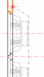
It will also make the hole too large for the driver. Those bevels have a narrow diameter that is the driver hole. Take the bevel away and th ehole will be the bevel depth too large a radius for the driver.
Here is a simple example of such a bevel for the A10p (18mm baffle) *. Take the bevel out and the driver pretty much falls into the box.
*(raises the question whether Bob rebated for the A10 with or without the bezel (without i hope as Alan’s A10PeN do not use them)).
There is also the issue of the 2 speakers being different, something i could not tolerate. The woofers would need to be mounted from inside the box and would be 18mm less the woofer bevel thickness further back.
dave
Attachments
And, to those of you who recommended that I take the baffle off, I think we urgently need an intervention. Wishing that level of discomfort on a fellow human being is an art form.
I think it is either that or get a fresh flatpak to replace the misassembled box. Easier, but pricier and somewhat wasteful.
I did spring a similar endeavor on Chris when i decided i had mistuned the 1st set of big Em-Kens. A lot of dust flew, took a couple hrs for him to finish. They did sound better.
dave
It will also make the hole too large for the driver. Those bevels have a narrow diameter that is the driver hole. Take the bevel away and th ehole will be the bevel depth too large a radius for the driver.
Here is a simple example of such a bevel for the A10p (18mm baffle) *. Take the bevel out and the driver pretty much falls into the box.

*(raises the question whether Bob rebated for the A10 with or without the bezel (without i hope as Alan’s A10PeN do not use them)).
There is also the issue of the 2 speakers being different, something i could not tolerate. The woofers would need to be mounted from inside the box and would be 18mm less the woofer bevel thickness further back.
dave
This is a design from Curt but Anything Curt and I worked on together had a 1 1/4" - 1 1/2" thick front baffle so the inner baffle adds absolute strength It certainly won't allow any drivers to "fall in". I think the pictures back up my assessment.
I always bow to Curt's assessment so I concur with everything he said.
Jim
If I may humbly reply to Curt’s and Dave’s comments.
The baffle Alan installed backwards is a secondary baffle and the drivers are mounted to the front baffle. The front baffle was correctlY rabbeted for the drivers used. Also, I had no idea that Curt Campbell was on this site, or that Jim Holts was in cahoots with Curt.
The baffle Alan installed backwards is a secondary baffle and the drivers are mounted to the front baffle. The front baffle was correctlY rabbeted for the drivers used. Also, I had no idea that Curt Campbell was on this site, or that Jim Holts was in cahoots with Curt.
Wow! Curt and Jim both within 5 mins! Thanks for weighing in. I think of you as the Nelson Passes of the DIY speaker world. That is meant as the highest compliment to all implicated.
And thanks for saving me from compound disasters. I'm going to take the jigsaw route and hope for the best. Don't have a router yet. I'm looking at this one:
http://tinyurl.com/tz8gssv
Any better alternatives?
alanhuth,
Excellent advise given by Curt and Jim.
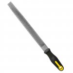
If you do not have a router or a jigsaw a more laborious path can be take a wood rasp (sample image attached) and remove the material. Once the sufficient amount has been removed, you can sandpaper the insides smooth if you want to.
A link to a short video on how use a wood rasp:
YouTube
And another one:
YouTube
Lot of elbow grease and bit of a work out... but possible.
Do wear a dust mask as there will be a lot of wood dust.As it has been mentioned before, this inner panel is there to add more strength to the front baffle, so the larger holes on the inside will not be a problem.
p.s. Kudos to Curt and Jim on WAW design.
Look forward to build updates from you alanhuth - may you get over the current build issue very quickly!Attachments
Last edited:
The baffle Alan installed backwards is a secondary baffle and the drivers are mounted to the front baffle.
OK, now i see. Thanx Bob. I thot the driver rebate was on the other side of those bevels. I rarely double a baffle, making sure it is adequately braced (baffle/back/top/bottom/driver are all coupled into an H-frame type "I-beam” structure, so never thot there might be a full-size supraBaffle.
dave
If I may humbly reply to Curt’s and Dave’s comments.
The baffle Alan installed backwards is a secondary baffle and the drivers are mounted to the front baffle. The front baffle was correctlY rabbeted for the drivers used. Also, I had no idea that Curt Campbell was on this site, or that Jim Holts was in cahoots with Curt.
Hi bobberner,
This is one of Curt's designs along with many others that I haven't been involved with.
The designs Curt and I have collaborated on since 2006 are as follows;
Statements Monitors
Mini Statements
Statements (original)
Statements II
Finalists (NLA)
Anthology's
Bordeaux
Travelers (upgraded Finalist replacement)
Statements Center (original)
Statements II center (perfect match with all of the designs and recommended)
I think that about covers it. Yes, we have had several designs over the years. Most are still available as kits through Meniscus. Mark can get you what ever you want at competitive prices.

HTH
Jim
For better or worse
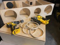
Well, I used a jigsaw and a 1" sanding sleeve. It is what it is. My current thinking is that, being lazy, I'm going to leave it as-is. As the guilt sets in after gluing on the outer baffle, I'll probably bondo up the missing bevel to match the one on the good speaker, even though the Designer Himself says it's probably not necessary.
Thanks to everybody for helping me get past this little panic. Back to work next weekend, with any luck.
Attachments
Halcyon - next challenge - Bi-AMP
I’ve been fascinated by the theories of Earl Geddes regarding subwoofers, and I thought that it might be fun to try to see if I can integrate the woofer section of these speakers in with my subwoofers. I have a mini-DSP, REW, etc. to play with. I bought the crossovers assembled from Madisound and they said bi-amping was possible, but maybe not the best idea. They also said I’d need two dual binding post boxes to do it.
Dave Dlugos very generously guided me through how this would have to be wired and he produced a lovely diagram which made it very clear (attached).
I decided I didn’t want to mess with another rebate for another binding post box, so I came up with an approach, which I hope will work. What I’d like to do is mount some sort of jumper/connection breadboard in the crossover box which acts as the base for the speaker under the Main cabinet. That would allow me to plug in jumpers to switch from bi-amp to passive x-over at will. Attached is a diagram of how I think that might work. I would then have 2 4-wire Neutrik/SpeakOn connectors between the crossover box and the speaker box.
I’m looking for help in two areas:
1) Do you guys think this will work? Am I overlooking something? Any better ideas?
2) What would you recommend I use for the breadboard/jumpers?
Thanks in advance for your continued support and advice. I really appreciate it.
Attachments
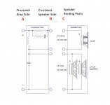
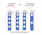
For clarification: Right now each speaker has one binding post cup with four connectors. I did not want to try to cut out a rebate for a second 4-post cup in each speaker. The goal is to use one 4-post cup for both bi-amp mode and passive crossover mode.
In bi-amp mode, I would connect the top two posts to amp/miniDSP for the Alpair full-range and connect the bottom two posts to the amp/miniDSP for the woofers.
In passive mode, I would bridge the two left-hand posts with a copper strap, same for the right, and then attach one left post and one right post to the standard amplifier.
Last edited:
For clarification: Right now each speaker has one binding post cup with four connectors.
Then why muck around. Wire the woofers to one, the midTweeter to the other. Then run wires from the external XO to the speaker or from the ams to the speakers when biamping.
You can use the 2nd set of 4 posts on the XO box (you will also need a single pr for input.
dave
I guess I’m mucking around because I don’t really have room for a 4-post cup plus a 2-post cup on the base unless they are mounted sideways, on the side of the cabinet. WAF issues and basic aesthetic issues with that. I don’t want it to look like a science project.
I’m sure there’s a way, but I‘D prefer not to have 6 wires plugging into the base of each cabinet., on the side.
So, given that I may be making this more complicated than necessary, does anybody have any suggestions for how i could do this breadboard thing. Or better?
I’m sure there’s a way, but I‘D prefer not to have 6 wires plugging into the base of each cabinet., on the side.
So, given that I may be making this more complicated than necessary, does anybody have any suggestions for how i could do this breadboard thing. Or better?
That sounds like a reasonable compromise. I could live with that if I have to. Maybe a Neutrik plug at one end and 4 banana plugs at the other so I can take those wires off if in bi-amp mode?
But I’d still like to explore the breadboard/jumper option. Any suggestions for what types of connectors or junction boxes to use? There must be something out there that’s easy and ready to go.
But I’d still like to explore the breadboard/jumper option. Any suggestions for what types of connectors or junction boxes to use? There must be something out there that’s easy and ready to go.
- Home
- Loudspeakers
- Multi-Way
- Curt Campbell's Halcyon build thread