Oh and I forgot to mention before, you made the mistake with your lpad that I also made. It should be after the capacitor, not before it.
It will likely mean you need to change the cap value, and could change the transfer function somewhat, but the reason for putting it after is that if it is before, you end up with around 10.8 ohms to ground, in parallel with your woofer which drops it's overall impedance quite a bit.
If it is after the cap then the woofer never sees that low impedance in parallel with it and your amp will have a much easier time.
Tony.
You will have a time aligned system
First Order crossovers are great.
When you are told that first order is wrong, ask have they ever built one with drivers designed for the purpose.
Much cheaper as well.
Be willing to try different cap values other than what a program recommends.
P")
First Order crossovers are great.
When you are told that first order is wrong, ask have they ever built one with drivers designed for the purpose.
Much cheaper as well.
Be willing to try different cap values other than what a program recommends.
P
Great to see you posting P
drewrf phoenix358 is who suggested to me originally to try just the cap on the tweeter and the woofers running full range. He probably has more experience with morel drivers than anyone on this forum, and I believe may have had a hand in the design of the semi-horn loaded tweeters for the purposes of time alignment.
Tony.
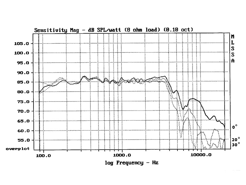
The woofer has a nice rolloff starting around 4000Hz with a small peak around 8000Hz (cone breakup?). My idea would be to address this with a 1st-order filter around 5-6kHz to make sure it is far enough down it will be inaudible
A first-order low-pass filter at 5.5 kHz is not going to have a lot of impact on an 8 kHz resonance but looking at the FR chart, it is more of a dip at 6 kHz than a specific peak at 8 kHz. Anyway, I would cross over lower and go for second order.
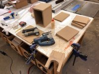
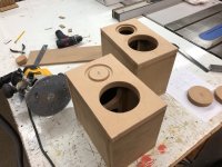
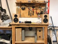
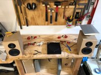
Alright I found some time to finally get some cabinets built, decide on some ports and get to playing with some different crossovers after ordering some parts. To my luck it seems that the models/graphs Morel provide are accurate because my computer modeled crossovers really sang. I first built the 1st order crossover and really enjoyed it. I listened to it for about a week. It had a few weird phase issues as I moved around the room but had a really engaging punchy sound. I loved the simplicity of it. I am amazed with the bass the 538 woofers can produce. Everything sounded like it was where it was supposed to be.
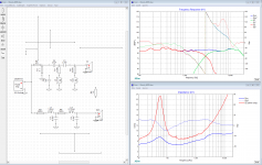
The 1st order was great and enough so that I trusted the computer modeled crossover of the 4th order that I had also liked that I rolled the dice and spent the money to order that parts for it. I built it last weekend. The results are a work in progress, but phenomenal. With the phase coherency of the drivers through the crossover the inner detail and transients just oozed out. Also the weird nulls at certain points in the room were much less apparent. It was another one of the HiFi nirvana moments when you start noticing little details in songs you didn't before. That being said, they are a little fatiguing after about 20 minutes. Reviewing my crossovers and graphs I think I understand why. First, I am testing them in my shop which has about 0 sound absorption. Second, reviewing the graphs it has a bit of a smiley face plot to it whereas the 1st order had a nice very gradual roll off of the highs. I went back to my modeling and came up with the revised crossover attached which has a better response curve and near perfect phase alignment throughout the entire crossover range. I ordered the parts I tweaked last night and am excited to see what I have cooked up when they arrive Friday. If I had to pick one of the two as the are now, I would pick the first order. I heard something I really loved in the 4th order though and am going to try and chase that for the time being.
The 1st order was great and enough so that I trusted the computer modeled crossover of the 4th order that I had also liked that I rolled the dice and spent the money to order that parts for it. I built it last weekend. The results are a work in progress, but phenomenal. With the phase coherency of the drivers through the crossover the inner detail and transients just oozed out. Also the weird nulls at certain points in the room were much less apparent. It was another one of the HiFi nirvana moments when you start noticing little details in songs you didn't before. That being said, they are a little fatiguing after about 20 minutes. Reviewing my crossovers and graphs I think I understand why. First, I am testing them in my shop which has about 0 sound absorption. Second, reviewing the graphs it has a bit of a smiley face plot to it whereas the 1st order had a nice very gradual roll off of the highs. I went back to my modeling and came up with the revised crossover attached which has a better response curve and near perfect phase alignment throughout the entire crossover range. I ordered the parts I tweaked last night and am excited to see what I have cooked up when they arrive Friday. If I had to pick one of the two as the are now, I would pick the first order. I heard something I really loved in the 4th order though and am going to try and chase that for the time being.
Attachments
Drewrf
The reason you said,
"near perfect phase alignment throughout the entire crossover range."
is because the drivers are time aligned before you start work on the crossover.
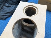
Physically, the drivers are already time aligned on the baffle. That is why these are fun to play with.
P
The reason you said,
"near perfect phase alignment throughout the entire crossover range."
is because the drivers are time aligned before you start work on the crossover.
Physically, the drivers are already time aligned on the baffle. That is why these are fun to play with.
P
Drewrf
The reason you said,
"near perfect phase alignment throughout the entire crossover range."
is because the drivers are time aligned before you start work on the crossover.
Physically, the drivers are already time aligned on the baffle. That is why these are fun to play with.
P
Yes, that is why I chose to mount them as I did. I saw somewhere else in I think this forum someone mention that this pair aligned like this would be fun to play with. I have never had the chance to play with time aligned drivers. So far I'm amazed.
Oh and I forgot to mention before, you made the mistake with your lpad that I also made. It should be after the capacitor, not before it.
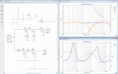
I swapped this and it helped fix a null while also raising my speakers impedance from 4 to 8 ohms, but now I need to order some more parts (arg!).
I do have one question though. It made the phase alignment a little less sweet on the lower end of the crossover. I was playing around and correcting my fake resistors that show the resistance of the coils and noticed that if I R5 to 2.7 ohm about coil+2.5ohms it totally flattened it back down with the system and tweeter phase while having almost zero effect on the frequency response. Is this something people do? It seems like it would lessen the effect of the coil, but the graph didn't show that. Although, it may not be common practice to do so and perhaps isn't modeled into Xsim? Is this something people do and I am unaware of?
Interested in anyones take on this.
Attachments
Yes you have discovered one of the secrets of crossover design resistance in series with shunt coils and shunt caps can be used to tune the phase matching. In the case of coils it actually can be a cost saver too as you can buy a coil with higher DCR (which are cheaper).
On the topic of DCR it looks like you are using an 18Ga coil for the 1.5mH. with a DCR of 0.62 ohms. This will be reducing the overall sensitivity of your speaker. Erse has a 14ga 1.5mH inductor which has DCR of .28 ohms. You'd probably need to go to a cored inductor (laminated if you went down that path) to get lower. Of course halving the resistance pretty much doubles the cost (laminated core inductors not so much).
You can have a play in the sim and see how much difference it would make, you would need to adjust the tweeter lpad as well.
Tony.
resistance in series with shunt coils and shunt caps can be used to tune the phase matching. In the case of coils it actually can be a cost saver too as you can buy a coil with higher DCR (which are cheaper). On the topic of DCR it looks like you are using an 18Ga coil for the 1.5mH. with a DCR of 0.62 ohms. This will be reducing the overall sensitivity of your speaker. Erse has a 14ga 1.5mH inductor which has DCR of .28 ohms. You'd probably need to go to a cored inductor (laminated if you went down that path) to get lower. Of course halving the resistance pretty much doubles the cost (laminated core inductors not so much).
You can have a play in the sim and see how much difference it would make, you would need to adjust the tweeter lpad as well.
Tony.
Wintermute, glad to hear that. I know my efficiency on this speaker isn't fantastic, but I plan on driving it with a beefy Adcom GFA 545II and live in an apartment so I have enough power for my SPL req.
I am going with slightly cheaper coils to keep cost down. I played with the next step up and the gain in efficiency was negligible, especially in comparison to the cost. I'd also prefer to stick to aircore inductors for fidelity.
I am going with slightly cheaper coils to keep cost down. I played with the next step up and the gain in efficiency was negligible, especially in comparison to the cost. I'd also prefer to stick to aircore inductors for fidelity.
 I wasn't sure how much of a difference it would make but thinking about previous sims I've done your result isn't surprising.
 - Status
- This old topic is closed. If you want to reopen this topic, contact a moderator using the "Report Post" button.
- Home
- Loudspeakers
- Multi-Way
- Morel 2-Way Design