For a single driver and a single tone, it's pretty clear and straightforward that bog standard linear theory will predict what the I/V curve will look like. Where it starts to fall apart a bit is because of the cabinet and room. If you start a sine quickly at resonance for example, the amplitude will build during the first few cycles. Current will be slightly higher during that buildup but not crazily so.Now THAT'S what I'm talking about...or could be. I gotta get some equipment together to test things. Though it seems even from a static curve, there are rough equivalent impedances presented to amplifiers. Maybe we need to back to the days when KEF showed a smiling Richard Small telling us they had made our amps twice as powerful!When I mentioned that to him once he looked embarrassed, though considering some thread contents here he needn't have been methinks.
Trying to model the transient nature of a cab with the air mass, t-line time delay, impedance mismatch at the port, rather daunting set of equations.
Combine all this transient behavior with three drivers and drive with actual music...the analytical equations start to go beyond most humans to understand. That is why this ERPD is a step in the right direction, it acknowledges the fact that reactive loading is by nature, a return of energy, and that amplifiers should be designed to handle it. Some designers add more silicon and aluminum, some use foldback circuitry.
Where they fall short is using sines only, as that exercises one driver at a time in essence. Joe R's approach is to even the load for the amp, but again that is only sine testing. Amplifiers have to drive two or three parallel loads simultaneously. That is where the I/V display comes in. That shows you what the amp has to do for the complex signal of music. The use of a foldback to cover a single driver reactive load curve with margin can easily be insufficient when three frequency independent loads are paralleled on the amp, as the current can easily exceed the foldback threshold during hard music.
Edit: as you can see, designing a speaker for uniform sine impedance across the band looks nice on paper, but may not look nice to the amplifier during music. And I believe that for most here, music is the intended reason for the speaker.
Ps. Given the true nature of what goes on with speakers, it is important to give a shout out to people like Earl Geddes, Joe R, many others who give us excellent sounding speaker systems through hard work. As well as amp designers like John Curl who led the way.
Jn
Last edited:
Matti Otala proposed that the dynamic drivers could act as generators and under certain transient conditions look like almost short circuits.
It turns out that real world speaker drivers are so inefficient motors that the effect is negligible.
Steady state low impedances due to poor crossover design, especially with transformers such as in ribbon tweeters is another matter.
It turns out that real world speaker drivers are so inefficient motors that the effect is negligible.
Steady state low impedances due to poor crossover design, especially with transformers such as in ribbon tweeters is another matter.
Years ago I had a pair of Richar Allen HP12B and if you push the cone with your hand the suspension was very flexible but if you short circuit the voice coil it was a lot stiffer.. . and if you wire both in parallel and push the cone with your hand the second speaker move.( right hand rule & left hand rule ) Back EMF and induced voltage really exist.
So they must be present in a '' working '' speaker and will affect impedance and current.... also the enclosure and the loading will affect the motion of the speaker and will change impedance curves... ( typical bass reflex analysis shows that ) How low will the impedance go .... nightmare ...... again.
So they must be present in a '' working '' speaker and will affect impedance and current.... also the enclosure and the loading will affect the motion of the speaker and will change impedance curves... ( typical bass reflex analysis shows that ) How low will the impedance go .... nightmare ...... again.
It is not clear to me why low efficiency precludes that.Matti Otala proposed that the dynamic drivers could act as generators and under certain transient conditions look like almost short circuits.
It turns out that real world speaker drivers are so inefficient motors that the effect is negligible.
Steady state low impedances due to poor crossover design, especially with transformers such as in ribbon tweeters is another matter.
While Otala may have proposed that, did he ever actually show it by measurement?
Very odd that he would say that however, as it sounds like he is proposing that a speaker might actually be a reactance? Go figure..
Jn
That would be EPDR.That is why this ERPD is a step in the right direction, it acknowledges the fact that reactive loading is by nature, a return of energy, and that amplifiers should be designed to handle it.
Experts - sheesh!
That would be EPDR.
Experts - sheesh!
Hey, give me a break.. I still have problems remembering who delivered the ICE....Moe,Larry, Curly, or ELI the ICE man.
Jn
That would be EPDR.
Not quite, my impression from the references posted was that EDPR was derived from sin sweep measurements and none of these non-minimum phase issues are accounted for. My question is, does accounting for them have any added bearing on the amplifier's contribution to the problem? I consider "back EMF" as that which is caused by outside agency such as reflected sound or mechanical waves reflected the suspension, etc. which due to the delay fall out of conventional analysis.
BTW jn guess what I found unpacking yesterday, the current sense resistor you made. This would not be hard to instrument on say a single driver in an enclosure, I would use something like raised cosine tone bursts or short bursts of closely spaced tones. I tried this long ago looking for IM frequencies with level on tweeters.
It is also worth remembering that ribbon, electrostatic, and compression drivers are going to have very different issues.
He was correcting my error, the nomenclature is really EPDR..Not quite, my impression from the references posted was that EDPR was derived from sin sweep measurements and none of these non-minimum phase issues are accounted for. My question is, does accounting for them have any added bearing on the amplifier's contribution to the problem? I consider "back EMF" as that which is caused by outside agency such as reflected sound or mechanical waves reflected the suspension, etc. which due to the delay fall out of conventional analysis.
Back EMF is the voltage generated as the coil moves through the field.
When it does not match expectations of the amplifier, current is drawn in an attempt to correct that error. But yes, the other stuff causes it to fall out of conventional analysis.
That was a few years back, no? Be careful, no heatsinking so don't burn it..I forgot, was it 1 ohm or .1 ohm?BTW jn guess what I found unpacking yesterday, the current sense resistor you made. This would not be hard to instrument on say a single driver in an enclosure, I would use something like raised cosine tone bursts or short bursts of closely spaced tones. I tried this long ago looking for IM frequencies with level on tweeters.
Yup. That is why I proposed a box that has a good low value CVR internal, and some DSP horsepower to calculate dissipated vs returned power. 40 years ago, that was a trivial thing using an analog multiplier chip. Simple multiplication of V and I, when the product is positive, dissipation in load, negative means returned to the source.It is also worth remembering that ribbon, electrostatic, and compression drivers are going to have very different issues.
jn
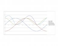
This is output stage dissipation when the load is a pure inductance. it's all normalized to 1 for simplicity of explanation.
Dark blue output voltage. Red is load current, 90 degrees lagging.
Major notes:
1. the peak pass dissipation is not during peak voltage nor peak current, but at 30 degrees in this example.
2. it is not zero when the output voltage is zero.
jn
Dark blue output voltage. Red is load current, 90 degrees lagging.
Major notes:
1. the peak pass dissipation is not during peak voltage nor peak current, but at 30 degrees in this example.
2. it is not zero when the output voltage is zero.
jn
Attachments
Last edited:
That was a few years back, no? Be careful, no heatsinking so don't burn it..I forgot, was it 1 ohm or .1 ohm?
0.1, if you remember I used it when I measured the damping of a woofer open and shorted as a demo. I still have the big super-magnets that float down a 1" copper pipe.
0.1, if you remember I used it when I measured the damping of a woofer open and shorted as a demo. I still have the big super-magnets that float down a 1" copper pipe.
I have difficulty remembering anything before this morning's coffee..
jn
A simplistic response used in an attempt to divert from reality.
Jn
Earl,
My apologies.
I did not react well to you treating me as a troll.
For what I do, I am here to explain. For what I do not, I am here to learn.
At some point, you may decide that my understandings are of value and you will benefit. If not, that is not my concern.
I post for others to learn. If that happens, great. If not, I cannot worry. Life is too short.
John
It's good that you apologized because you were just about to get a bold response and addition to my "ignore" list.
You may be good at what you do, but I am very good at what I do. My expertease is math and loudspeakers, and while you may be trying to educate others, it is important that someone correct you when you say things that are wrong. You won't find me wrong about math and loudspeakers very often, so it is well that you should heed my comments.
What is lost is this...
Music is not steady state. It is transient by nature.
Describing any speaker system using a swept sine, while useful, is not far enough. Eventually, some will go further.
Jn
Steady state versus transient make no difference in a linear system and as I have said, loudspeakers are very close to be perfectly linear. Not that they all are, but this feat can certainly be done. My designs are virtually perfectly linear and so linear system theory holds. If it doesn't hold in your systems then they should be redesigned so that it does.
You might want to read my papers on loudspeaker nonlinearity because I have done probably more on that topic than anyone. It turns out not to be a big issue anymore as designers work to minimize these problems.
Last edited:
It is not clear to me why low efficiency precludes that.
While Otala may have proposed that, did he ever actually show it by measurement?
Very odd that he would say that however, as it sounds like he is proposing that a speaker might actually be a reactance? Go figure..
Jn
Because of the back EMF a loudspeaker does look reactive to the amp. That is simply what all this EPDR is all about. WHen a loudspeaker pushes current back into the very low output resistance of a voltage amp then this will look exactly like a reactive impedance. Back EMF and the impedance curve are one and the same thing and talking about them as different is going to confuse the issues.
As a driver approaches its resonance from below it looks like a giant inductor, then at resonance a very large resistor, followed by a large capacitor. These things need to be handled by the amplifier and most do this very well, especially for woofers since this is at a very low frequency. A tweeter with a crossover may be problematic if not done properly. But since a compression driver is so much more efficient than a woofer it almost always has a resistive pad, which tends to flatten its reactive components as seen by the amp.
It's good that you apologized because you were just about to get a bold response and addition to my "ignore" list.
Keep in mind, I did not apologize because of a fear of a bold response nor being ignored by you.
I did so because it was the right thing to do.
Which is fine, I've no information one way or the other regarding your product. I would like to discuss how your suspensions do not change spring constant, and how you keep Le(x) absolutely rock stable through full excursions. If it's just small signal, that is fine as well.Steady state versus transient make no difference in a linear system and as I have said, loudspeakers are very close to be perfectly linear. Not that they all are, but this feat can certainly be done. My designs are virtually perfectly linear and so linear system theory holds.
However, the discussion has been about output stage dissipation. Using the VI plots, watch how actual music displays. Total chaos. Impossible to actually calculate even though it's linear. While you may be happy w/r to the speakers, this discussion is really about the amps. And, a discussion of the severity of amplifier dissipation is not about being gentle with the drivers. And as you earlier stated, you do not concern yourself with the amp.
What I work in is so far beyond that kind of simple model that it isn't even funny. The devil is in the details when working kiloamps and 5-10 tesla, even the room temp stuff needs 5 and 6 digit magfield accuracies. The "real" things I mentioned prior are what have to be considered and dealt with to reach targets. I mention it here because I see speaker driver manufacturers attempting to solve the same basic problems.If it doesn't hold [linear system theory] in your systems then they should be redesigned so that it does.
Yet the big driver manu's still wrestle with it. Either they ignore your work, or their requirements fall outside it. My guess, at high power they cannot follow what you suggest.You might want to read my papers on loudspeaker nonlinearity because I have done probably more on that topic than anyone. It turns out not to be a big issue anymore as designers work to minimize these effects.
Vere are your papers? Web?
Do you design for voltage or current drive on your product?
Do you have plots of your product using either available to peruse?
jn
Because of the back EMF a loudspeaker does look reactive to the amp. That is simply what all this EPDR is all about. WHen a loudspeaker pushes current back into the very low output resistance of a voltage amp then this will look exactly like a reactive impedance.
That is what I just said, and why I provided the plot.
I didn't see anybody refer to them as different. They are totally related.Back EMF and the impedance curve are one and the same thing and talking about them as different is going to confuse the issues.
Agreed in principle, that's why I like them and why I like FL horns for woofs.But since a compression driver is so much more efficient than a woofer it almost always has a resistive pad, which tends to flatten its reactive components as seen by the amp.
For a three way using direct radiators, I can see why the effort to develop some characterization method such as EPDR. At this time, their efforts are in the infancy, but I do like the concept of understanding reactive load impact on amps.
jn
Last edited:
DRiver manufacturers follow the trends in their advertising. You will find that Alex Voishvillo at JBL is in complete agreement with me.
Le variation with excursion is small if the magnetic circuit is symmetric WRT the voice coil, and really its Le(I) that is the bigger problem. This can be resolved with a shorting ring. And a "good" driver has both of these features.
Since I no longer make speakers I don't publish anything anymore, but all that I have is available on my site below, or at the AES library.
That is what I just said
jn
But you said:
Very odd that he would say that however, as it sounds like he is proposing that a speaker might actually be a reactance?
So that is not what you just said.
Ah, I see. There needs to be a tongue in cheek emoticon. Sorry about that.But you said:...
So that is not what you just said.
jn
As long as the return structure is on one side of the vc, there will be Le(x) variation. Severely underhung can be used, as can pole tip profiling.Le variation with excursion is small if the magnetic circuit is symmetric WRT the voice coil
, and really its Le(I) that is the bigger problem. This can be resolved with a shorting ring. And a "good" driver has both of these features.
A shorting ring uses a different mechanism from what happens on the front side of the structure. I see it used for Le(x).
Le(I) is certainly a concern as most tend to enter non linear permeability due to cost constraints. A shorting ring is both coil position and frequency dependent, but not effective against I effects, but rather, dI/dt as well as the velocity based modulation effects as an energized vc is dragging through the environment..
Since I no longer make speakers I don't publish anything anymore, but all that I have is available on my site below, or at the AES library.
A shame, as you not developing new speakers is everybody's loss.
Cheers, John
ps..perused your site. Lots of good stuff on perceptions and horn waveguides, but I find nothing on what we have been discussing. And I forgot your stain glass work, which I also did back in the day. Gave up, as I was depleting the band aid inventory at the local drugstore.
Last edited:
- Status
- This old topic is closed. If you want to reopen this topic, contact a moderator using the "Report Post" button.
- Home
- Loudspeakers
- Multi-Way
- Is speaker impedance ever less than DC resistance, even under transient conditions?