How about using one of the commercially available waveguides like the Visaton WG-148R (148 mm diameter) or the Monacor WG-300 (168 mm diameter)? Heissmann Acoustics has tested several tweeters on these waveguides with very good results. LINK. Troels Gravesen also has information on using the Monacor waveguide with various tweeters, including the ScanSpeak D3004/660000 and D3004/664000. LINK
Well honestly, I am not a big fan of horns in loudspeakers. Just don't like the way they look and they take a lot of space on the baffle(I prefer my drivers close to eachother). Although I must admit that the directivity control for high frequencies can be superior.
Then I discovered the directivity control of the DXT tweeter and was quite amazed how good the directivity control was for such a small wave guide. Besides that I found it really fascinating how diffraction could be used constructively instead of doing harm. That's when I started to try and copy the SEAS DXT design.
I understand your feelings about the looks. That's why I prefer the smaller Visaton over the Monacor. The Visaton actually looks nice when paired with an 8" or larger driver. Good luck on your endeavor!
Hi,
As the simulations of the DXT presented in the German DIY-forum have been mentioned here, I'll post the most important images from the Waveguide Thread on the DXT here.
Post #205 gives the profile of the DXT (buest guess, i.e. measurement taken from a DXT).
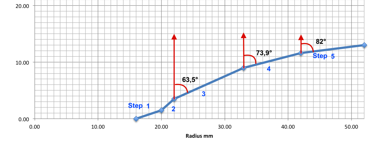
The profile is given as 'Steps 1-5'.
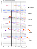
The next image gives the impact of the 5 'Steps' - one after each other - on the directivity of the dome tweeter, starting with the dome only (Nur Kalotte):

You can easily see, what the addition of the single steps do to the directivity (0-90°, 15°-steps if I remember correctly). The vertical help-line at 3kHz is given to show how the additional steps shift the directivity control to lower frequencies. Please note that these simulations have been done in an infnite baffle. Directivity control below 3kHz will be affected as well by the applied baffle width...
The horizontal line at 90dB is given to show th SPL increase between roughly 2 to 10kHz with addition of the single 'Steps' of the DXT waveguide.
For some tweeters you can remove the faceplate and directly mount your tweeter of interest to a waveguide... I do not know about the D3004/66400 though.
If you intend to simulate/construct your own DXT-related WG for the D3004/66400 you do not have to go for ABEC as soon as your WG is round, i.e. axisymmetric. You can use AxiDriver instead, which is relatively easy to use (at least compared to AEBC).
Quote:
Originally Posted by EADGE View Post
Gaga made some ABEC simulations of this waveguide in a german forum. He is a member in this forum too, very busy but always helpful.
I googled a bit and found the following article:
Open source Waveguides for CNC & 3D printing!
The forum he refers to is very helpful and is what I initially was looking for. I am going to try to simulate the waveguide with the parameters given on that forum!
Thanks alot!
As the simulations of the DXT presented in the German DIY-forum have been mentioned here, I'll post the most important images from the Waveguide Thread on the DXT here.
Post #205 gives the profile of the DXT (buest guess, i.e. measurement taken from a DXT).
The profile is given as 'Steps 1-5'.
The next image gives the impact of the 5 'Steps' - one after each other - on the directivity of the dome tweeter, starting with the dome only (Nur Kalotte):
You can easily see, what the addition of the single steps do to the directivity (0-90°, 15°-steps if I remember correctly). The vertical help-line at 3kHz is given to show how the additional steps shift the directivity control to lower frequencies. Please note that these simulations have been done in an infnite baffle. Directivity control below 3kHz will be affected as well by the applied baffle width...
The horizontal line at 90dB is given to show th SPL increase between roughly 2 to 10kHz with addition of the single 'Steps' of the DXT waveguide.
Please note that the WG-profile at the WG-throat has a hughe impact on the directivity at high frequencies, i.e. you have to carefully check, how the dome of a tweeter is mounted in its faceplate and how this 'profile contributes to directivity control. Most tweeter domes are not exactly placed on top of the faceplate, but somehow recessed, introducing a 'step' around 1-3mm already. This 'step' has a hughe impact on directivity at very high frequencies already and should be considered when mounting the tweeter to a waveguide.A tweeter that has caught my eye is the SEAS H1499-06 27TBCD/GB-DXT. After some research I am quite fascinated by the use of constructive diffraction (instead of destructive). I want to use this wave guide, but I don't like the tweeter itself. I'd prefer to use a beryllium dome (I currently have my eye on the Scanspeak Illuminator D3004/66400).
For some tweeters you can remove the faceplate and directly mount your tweeter of interest to a waveguide... I do not know about the D3004/66400 though.
If you intend to simulate/construct your own DXT-related WG for the D3004/66400 you do not have to go for ABEC as soon as your WG is round, i.e. axisymmetric. You can use AxiDriver instead, which is relatively easy to use (at least compared to AEBC).
Attachments


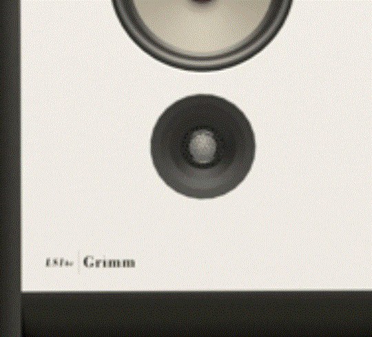
Seas produces a DXT with Be dome for the Grimm LS1. I think they use the dome from this tweeter:
E0058-06 T29B001
Faceplatemounting screws is also changed from front to back:
E0058-06 T29B001
Faceplatemounting screws is also changed from front to back:
Attachments
Most models of SEAS have interchangeable parts, eg. coil with copper pole piece, fluid, dome material, dustcap, frontplate etc.. SEAS uses this to serve loudspeaker manufacturers just what they want. Finnish Gradient is a loyal customer.
DESIGN PHILOSOPHY
DESIGN PHILOSOPHY
Last edited:
As the simulations of the DXT presented in the German DIY-forum have been mentioned here, I'll post the most important images from the Waveguide Thread on the DXT here.
Post #205 gives the profile of the DXT (buest guess, i.e. measurement taken from a DXT).
This is one of the threads I found when googling you (someone else mentioned that that had done work on this topic). I'm quite happy with a summary! Thanks for the elaborated reply.
If you intend to simulate/construct your own DXT-related WG for the D3004/66400 you do not have to go for ABEC as soon as your WG is round, i.e. axisymmetric. You can use AxiDriver instead, which is relatively easy to use (at least compared to AEBC).
Earlier in this topic mentioned that straight up copy pasting the design onto the D3004/6640 was not a great plan, since the size of the circles and the depth are designed for the tweeter. The concept of using diffraction edges for directivity control is what the patent is for.
For now I am going to try and "redesign" the DXT concept for the D3004/6640 tweeter. I'll just use the dimensions of the DXT tweeter as a starting point.
Seas produces a DXT with Be dome for the Grimm LS1. I think they use the dome from this tweeter:
E0058-06 T29B001
Faceplatemounting screws is also changed from front to back:
This is one of my favorite loudspeakers. I quite admire their design philosophy as well. I am not very certain if it is the same tweeter as the E0058-06 T29B001. Grimm's website states that they have co-developed the tweeter with SEAS. Though it could be that they just designed a new waveguide for it.
I intend to mount the tweeter in a similar way as the Grimm LS1 Be.
All models of SEAS have interchangeable parts, eg. coil with copper pole piece, fluid, dome material, dustcap, frontplate etc.. SEAS uses this to serve loudspeaker manufacturers just what they want. Finnish Gradient is a loyal customer.
DESIGN PHILOSOPHY
Yes, I could've done this and bought their beryllium tweeter. However the SEAS Be Tweeter is already very expensive (And I have never heard it before). Besides SEAS is not willing to sell me the DXT tweeter separately. I have already contacted them about it.
Besides, after posting about this on DIYaudio I learned a lot about waveguides and software that helps me designing them. Apparently there comes more to designing waveguides than blatantly copy pasting someone else's design. If I make it myself I will learn how to design a DXT waveguide, I will get a more appealing look (by being able to rearmount the waveguide and tweeter), I will spend less money (less than using the SEAS tweeter), if it turns out right the performance will be better than a copied design. Downsides, it costs way more time, possibility of going wrong is a lot higher.
To me the upsides of doing it myself outweigh the downsides.
As for now I am going to simulate the waveguide with the help of Axidriver. It has been recommended several times. I have also gotten my hands on an older version of COMSOL, but it's quite complex as it has many more features than I need.
Thanks everyone for the help!
For now I have enough information to keep on tinkering.
Alright, today I've had the time to play a little with AxiDriver. I started by using the same values as the Seas DXT driver (the values I posed in my 1st post).
These values turn out the be HORRIBLE for the tweeter I wanted to use (SS D3004/6640)! I'm glad I did the simulation first.
I have a few problems with Axidriver though. I can only use the simulation for one frequency at a time (well, you can for multiple but you can only see the result of one at a time).
The diagram itself is also quite strange. It uses two distances and colour for the amplitude. Personally I prefer frequency vs angle and amplitude in graded colours (Like this one: https://heissmann-acoustics.de/wp-content/uploads/dxt_mon_rly_directivity_hor.png)
I am also fine with the style of diagrams that Gaga posted earlier in this topic.
I tried changing the axis, but all it seems to do is change the name of the axis. Unfortunatly it does not change the parameter that is used to sweep.
I figured out that you need a second program; VACSviewer. Apparently you are supposed to be able to view different diagrams based on the calculations done, but I haven't figured out how this works yet. Somehow it doesn't copy the calculated data of Axidriver. Perhaps this is a limitation of the free version?
Troels gravesen also put de D3004/6640 in a waveguide. He also made nice drawings of mounting a waveguide onto it.ScanSpeak-Waveguides
Anyway, some progress is there, but still far from the destination.
There should not be an issue with the VACS Viewer in terms of communication with AxiDriver. Only missing feature should be saving of projects. However, you can export images from VACS viewer...
May be an issue wit the VACS-settings within AxiDriver? Or you may have to check the Box 'Auto Updates'
May be an issue wit the VACS-settings within AxiDriver? Or you may have to check the Box 'Auto Updates'
Viewer/Demo
VacsViewer is essentially the same application as VACS but does not allow for saving VACS-project-files. In this way VacsViewer serves as a viewer and as a demo. VacsViewer is free of charge and readily available at the VacsViewer-download-page...
There should not be an issue with the VACS Viewer in terms of communication with AxiDriver. Only missing feature should be saving of projects. However, you can export images from VACS viewer...
May be an issue wit the VACS-settings within AxiDriver? Or you may have to check the Box 'Auto Updates'
I managed to fix it. Quite the stupid mistake really. I forgot to check the settings in the Vacs tab.
The software is quite nice! I'm still a newbie when it comes to design waveguides. I'll have to do a bit more research about what the effects are of all the parameters (I've been changing values randomly, not really the engineers approach haha).
So I started working out some values and realised that the Re modifier and the Le modifier have quite a significant impact on the result. I can't seem to get my hands on these values through the datasheet.
The parameter is required for both the Klippel Method and the AkAbak. It is not required for low frequency, but that'd be inaccurate I assume since the waveguide will be for a tweeter.
Would I need something like a Clio Pocket for this to measure the nonlinearity in impedance? Or should I contact scan-speak about these parameters?
Would I need something like a Clio Pocket for this to measure the nonlinearity in impedance? Or should I contact scan-speak about these parameters?
I am curious why you want to include a model for the motor when your objective is to design a waveguide?
I am curious why you want to include a model for the motor when your objective is to design a waveguide?
Well I do not know how the calculation works and what parameters are required. I tried to fill in most of the parameters that I could find in the datasheet/STEP-file provided by Scan-Speak. The data about the motor was the only data I could not find. I started to simulate with some (random) values and see if it makes any difference in the result.
I noticed that there are quite significant differences in the results. Obviously I want my simulation to be as realistic as possible. That means I should provide the software with all the required information.
Since the required parameter has to do with the non-linear impedance and is (as far as I am aware) not provided, I assumed I have to measure the driver (with for instance a CLIO system).
Other small question: Does the software take the directivity of the tweeter in to account? I assume it doesnt, because it doesn't ask for a frd file.
I haven't used the AxiDriver software but looking at the tweeter examples on the website they don't appear to be including information about the motor. I would suggest studying them to see how it is disabled.Other small question: Does the software take the directivity of the tweeter in to account? I assume it doesnt, because it doesn't ask for a frd file.
The software assumes the motion of the cone is rigid. Don't know how the surround is handled where you would likely want to vary the imposed velocity with radius. The manual should say.
The directivity is calculated by the BEM software. You cannot specify it.
The software assumes a part (50% IIRC) of the surround to contribute to sound emission...The software assumes the motion of the cone is rigid. Don't know how the surround is handled where you would likely want to vary the imposed velocity with radius. The manual should say.
AxiDriver does. You actually need to define the driver motor (which you do not necessarily have to do with ABEC).I haven't used the AxiDriver software but looking at the tweeter examples on the website they don't appear to be including information about the motor.
ExpoRe and ExpoLe refine the 'motor' model of the applied driver (and of course have an impact on the high frequency SPL of the driver). Check the helpfile:So I started working out some values and realised that the Re modifier and the Le modifier have quite a significant impact on the result. I can't seem to get my hands on these values through the datasheet.
The parameter is required for both the Klippel Method and the AkAbak. It is not required for low frequency, but that'd be inaccurate I assume since the waveguide will be for a tweeter.
However, you do not have to give numbers here. You still can see the impact of a simulated waveguide contour on the directivity and SPL when you compare to directivity and SPL simulated for the identical driver in an infinite baffle...Voice coil
VC-Model switches the voice-coil model [more...]. Rg is the generator resistance by which you can take into account connection and wire losses [Rg] = ohm. The meaning of Re depends on the used VC-model, but can be regarded as the DC-resistance of the driver [Re] = ohm. The meaning of Le also depends on the model used, but is similar to an inductance [Le] = Henry. fre, ExpoRe, ExpoLe, Re2, Le2 depend on the model used. Units are [fre] = Hz, [ExpoRe] = [ExpoLe] = SCI, [Re2] = ohm, [Le2] = Henry.
- Status
- Not open for further replies.
- Home
- Loudspeakers
- Multi-Way
- DXT wave guide dimensions