Arguably, the main advantage of this layout, versus a conventional coax, is that you can manipulate the center-to-center spacing to change the beamwidth. For instance, if you used very very small midranges and packed them very tight, you could get something close to 180 degrees of beamwdith. As you widen the center-to-center spacing, your pattern is going to widen.
Surely widening the mid-mid spacing reduces the frequency at which off-axis cancellations happen, effectively narrowing the average dispersion, no?
A co-axial 15" 2-way would give much better matching of directivity than a normal dome as tweeter. Even SEAS DXT doesn't give directivity below 2khz and it cannot play down to 1kHz
15" coax is old school, check eg. Tannoy speakers! Modern application is eg. Taipuu 3-way, crossover design by kimmosto!
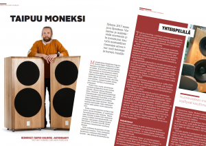

15" coax is old school, check eg. Tannoy speakers! Modern application is eg. Taipuu 3-way, crossover design by kimmosto!
Last edited by a moderator:
I do like that. Now I want to build more speakers, but I don't have anywhere to put them

Does the Edge-program model multi-driver respons fairly accurate?
Here's an animation done with xDir showing how the beamwidth changes with spacing.
Thanks for all the links, I've red them and been thinking about this quite a lot.
I have a question, if the drivers in this picture would be 6" in size, what would be the maximum crossover frequency, if the tweeter is on the middle.
Would it be 4500hz because the distance from the center of each midrange to the closest midrange center is only 6" ?

If that is not the right way, then it must be the distance to the most far away center which means 8.5" distance and a maximum of 3150hz crossover frequency.
Which one is correct?
I have a question, if the drivers in this picture would be 6" in size, what would be the maximum crossover frequency, if the tweeter is on the middle.
Would it be 4500hz because the distance from the center of each midrange to the closest midrange center is only 6" ?
If that is not the right way, then it must be the distance to the most far away center which means 8.5" distance and a maximum of 3150hz crossover frequency.
Which one is correct?
Looks like you calculated the frequency at CtC spacing of 1 wavelength by 13500 / 6 = 2250. That's good.
Then you multiplied by 2 to find maximum frequency at 1/2-wavelength spacing. That's bad - you went the wrong direction.
When 1/2 wavelength is 6", 1 wavelength must be 12". So the correct frequency is 13500 / 12 = 1125.
Then you multiplied by 2 to find maximum frequency at 1/2-wavelength spacing. That's bad - you went the wrong direction.
When 1/2 wavelength is 6", 1 wavelength must be 12". So the correct frequency is 13500 / 12 = 1125.
That's right, I made a mistake. It is 1125hz.
But isn't that the maximum crossover frequency only if you want listen to the speakers from all directions? And if you stay more on the front, let's say you are within 45 degree angle in the listening sector, then the crossover frequency can be more higher? At least that is what I understood after reading this from wikipedia:
"For any frequency (over the operating range of the midwoofers), the off-axis response exhibits different lobing patterns because of the vertical distance between the midwoofers, and as a function of the frequency and horizontal distance from the speaker.
At any off-axis listening position, although both midwoofers operate in phase (are time-aligned), the waves from each reach the listening position at different times (and therefore have a relative phase difference) - at frequencies where the time displacement between the two midwoofers corresponds to one-half of one wavelength, the outputs of the two midwoofers will null.
However, the time displacement itself is a function of the distance from the speaker and frequency, which means that the lobing for a given listening distance and off-axis position will be different at different frequencies."
Last edited:
Last edited by a moderator:
Thanks TNT, tried that and noticed it's a great free program. The serial I found on their web page.
Here I used 7" midranges mounted side by side and the microphone is 3 meters away and 1 meter to the side. No crossover is active in this simulation.
It looks like the response is good to about 2000hz like I thought

Here I used 7" midranges mounted side by side and the microphone is 3 meters away and 1 meter to the side. No crossover is active in this simulation.
It looks like the response is good to about 2000hz like I thought
Last edited by a moderator:
I now compared different single driver sizes and I had to go all the way to 18" to get a similar side response than with these four 7" drivers. That does not make much sense to me, I would have expected it to be in 15" range since there are quite big 'gaps' on the outer areas in the four driver configuration.
I wonder if the simulation oversimplified it, or is it really so.
I guess in this program you cannot turn the drivers facing different way, do you know any software that could?
I wonder if the simulation oversimplified it, or is it really so.
I guess in this program you cannot turn the drivers facing different way, do you know any software that could?
Not a circle but interesting all the same.
16 speaker array,worth anything? | Audiokarma Home Audio Stereo Discussion Forums
16 speaker array,worth anything? | Audiokarma Home Audio Stereo Discussion Forums
- Home
- Loudspeakers
- Multi-Way
- Midrange drivers in a circle?