Searched but found no similar thread
As per my crude drawing (Paint )
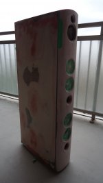
My goal here is to build a simple box and mount the driver conventionally with screw on the front baffle
Nothing new here.
Then, add a spacer of maybe 1/8" thick all around the front and add a 2nd baffle onto it (with a precise cut out for the driver basket)
I never tried but the way I see it, the vibration from the box won't be transmitted to the front baffle.
Does anybody tried such thing?
Benefit?
I got my idea on a Guitar forum
here the original design
Resulting look
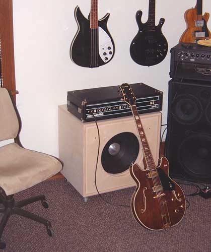
And the original post
Rickresource Rickenbacker Forum • View topic - Dyeing tolex
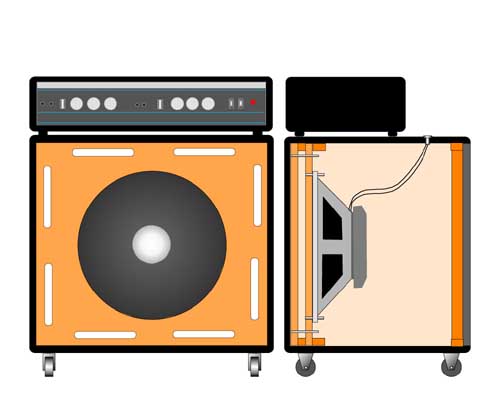
Ampeg did it too (I would just omit the bass reflex component)

As per my crude drawing (Paint )
An externally hosted image should be here but it was not working when we last tested it.
My goal here is to build a simple box and mount the driver conventionally with screw on the front baffle
Nothing new here.
Then, add a spacer of maybe 1/8" thick all around the front and add a 2nd baffle onto it (with a precise cut out for the driver basket)
I never tried but the way I see it, the vibration from the box won't be transmitted to the front baffle.
Does anybody tried such thing?
Benefit?
I got my idea on a Guitar forum
here the original design
Resulting look
And the original post
Rickresource Rickenbacker Forum • View topic - Dyeing tolex
Ampeg did it too (I would just omit the bass reflex component)
Last edited:
Way back on a long gone BBS a guy did it against mine and a few others explaining why it was a bad plan and once he'd done it he agreed that it ruined the bass line.
A driver 'wants' to 'feel' a rigid/massive work platform to maximize its electro-mechanical-acoustical efficiency, so one should make the cab rigid/massive enough to quell any vibration in its 'working' pass band; otherwise do what the pioneers did and rigidly mount the driver to a suitably rigid/massive 'platform' such as a massive timber or concrete floor or something similar and 'float' the baffle in front of it with a suitably soft material to seal this 'joint'.
These of course were large OBs, though IIRC there was a European brand at the time that did enclose some in permanent installs.
To get some idea how massive it can require, here's an ancient plywood 42" x 30" x 24" Altec small theater horn experimented with: Mass Loading ALTEC A7 VOTT 825 enclosures - drlowmu - High Efficiency Speaker Asylum
ALTEC VOTT A7- 800 , Concrete suggestions, Tweeter Horn - drlowmu - High Efficiency Speaker Asylum
P.S The vented double baffle from 1955: http://downloads.bbc.co.uk/rd/pubs/reports/1955-08.pdf
GM
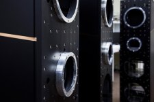
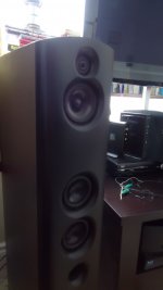
I did do something similar to your text, my drivers (in a line array) are bolted to an inner baffle while my outer baffle with exact driver cut-outs is connected to the enclosure:


Between the two baffles there is a damping layer of butyl. The inner baffle is "floating" between the enclosure and the outer baffle, as there is a neoprene layer between the enclosure and the inner baffle.
However in the pictures you posted it seems the inner/outer baffle construction is providing a bass port. That's not something I have, my cabinets are sealed.
Construction detail:
There are (at least) 2 issues with a double baffle system:
1. Mechanical coupling: If the 2nd baffle is touching the 1st baffle or any other part of the cabinet for that matter, the transfer of energy flows freely. On the other hand, if you decouple the 2 baffles with a viscoelastic material that resists the transfer of energy, like sorbathane or butyl (like wesayo has done above), then the 2 baffles will work together to form an effective system.
2. Choosing the correct implementation for the design: Are you actually building a single-way speaker like a guitar amp or sub? Or line array I guess too? Or a 2- or 3-way speaker? Because with a multi-way, you might also want to make sure you are isolating the mid and/or the tweeter from the larger mechanical energy produced by the woofers.
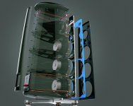
Magico for example has been using a double baffle system on some of their speakers for years. Woofers are rigidly attached to the 1st baffle, the mid is attached to the 1st baffle also but decoupled with a viscoelastic gasket and the tweeter is attached to the 2nd baffle also with a decoupling gasket. Another larger gasket is used between the 2 baffles. Don't ask me what the gasket material is because I don't know - I've never seen that mentioned before. Maybe someone else knows?
From my limited experience, the hardest part is designing how to attach the 2nd baffle while keeping it decoupled from both the 1st baffle and the rest of the cabinet too. Magico rigidly attaches the 1st baffle to the cabinet and then attaches the 2nd front baffle and the rear baffle together with threaded rods. The rear baffle may or may not also be decoupled - I'm not 100% sure on their latest design pictured below. Also attached are close-ups of the baffles.
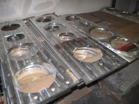
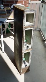
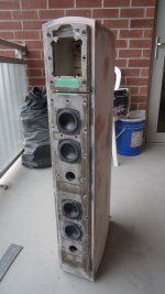
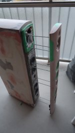
Recently, I gave the method a try as well but I took it a step further. It's a 3-way with a triple wall cabinet construction so that every separate chamber (3 of them) are also mechanically isolated from the outer cabinet walls as well. Green Glue was the choice between cabinet layers and sorbathane the choice between baffles. The 1st baffle has the woofers rigidly attached but is broken into 2 parts, 1 for the woofers and 1 for the mid to mechanically separate those two. The 2nd baffle has the mid and the tweeter rear mounted with sorbathane gaskets with additional sorbathane between the 2 front baffles at other points. I have 12 threaded rods holding the decoupled 2nd baffle to the back of the cabinet exterior layer. I did the outer layer in fiberglass, the inside layer out of cement and the middle layer out of rubber - the whole thing was a bit of an experiment to build a cabinet out of alternate materials and see how far I could take it. It worked better than I expected but lordy, lordy, it was one hell of a lot of work. Still have the final finishing to complete. See next 5 pics.
Btw in the case of the guitar amp you have shown, without mechanical decoupling, I think it would simply be better off with a single baffle and better cabinet bracing and stuffing.
1. Mechanical coupling: If the 2nd baffle is touching the 1st baffle or any other part of the cabinet for that matter, the transfer of energy flows freely. On the other hand, if you decouple the 2 baffles with a viscoelastic material that resists the transfer of energy, like sorbathane or butyl (like wesayo has done above), then the 2 baffles will work together to form an effective system.
2. Choosing the correct implementation for the design: Are you actually building a single-way speaker like a guitar amp or sub? Or line array I guess too? Or a 2- or 3-way speaker? Because with a multi-way, you might also want to make sure you are isolating the mid and/or the tweeter from the larger mechanical energy produced by the woofers.
Magico for example has been using a double baffle system on some of their speakers for years. Woofers are rigidly attached to the 1st baffle, the mid is attached to the 1st baffle also but decoupled with a viscoelastic gasket and the tweeter is attached to the 2nd baffle also with a decoupling gasket. Another larger gasket is used between the 2 baffles. Don't ask me what the gasket material is because I don't know - I've never seen that mentioned before. Maybe someone else knows?
From my limited experience, the hardest part is designing how to attach the 2nd baffle while keeping it decoupled from both the 1st baffle and the rest of the cabinet too. Magico rigidly attaches the 1st baffle to the cabinet and then attaches the 2nd front baffle and the rear baffle together with threaded rods. The rear baffle may or may not also be decoupled - I'm not 100% sure on their latest design pictured below. Also attached are close-ups of the baffles.
Recently, I gave the method a try as well but I took it a step further. It's a 3-way with a triple wall cabinet construction so that every separate chamber (3 of them) are also mechanically isolated from the outer cabinet walls as well. Green Glue was the choice between cabinet layers and sorbathane the choice between baffles. The 1st baffle has the woofers rigidly attached but is broken into 2 parts, 1 for the woofers and 1 for the mid to mechanically separate those two. The 2nd baffle has the mid and the tweeter rear mounted with sorbathane gaskets with additional sorbathane between the 2 front baffles at other points. I have 12 threaded rods holding the decoupled 2nd baffle to the back of the cabinet exterior layer. I did the outer layer in fiberglass, the inside layer out of cement and the middle layer out of rubber - the whole thing was a bit of an experiment to build a cabinet out of alternate materials and see how far I could take it. It worked better than I expected but lordy, lordy, it was one hell of a lot of work. Still have the final finishing to complete. See next 5 pics.
Btw in the case of the guitar amp you have shown, without mechanical decoupling, I think it would simply be better off with a single baffle and better cabinet bracing and stuffing.
Attachments
-
 M2.22.jpg107.7 KB · Views: 161
 -
 4 Flat and curved baffles.JPG488.2 KB · Views: 166
 -
 201206_q7_closeup2.jpg59 KB · Views: 151
 -
 cab.jpg204.9 KB · Views: 158
 -
 bfl1.JPG204.1 KB · Views: 169
 -
 rods.JPG189.9 KB · Views: 167
 -
 assembled raw.JPG155.3 KB · Views: 172
 -
 assembled painted.JPG162.8 KB · Views: 175
Thanks GM, wesayso and Jreave
Those are great, comprehensive answer.
Won't venture this direction anymore, it was for my quad 15" bass bin (~50hz-500hz)
The mass loading GM proposed, I've tried it and had good result (thru only with ~50pounds sandbag, seem like this Altec VOTT guy on the link really pushed the envelope at ~400 pounds per speaker.)
Jreave, fantastic build, is there a thread on those?
Seem like I'll go to hardware store soon 🙂
Thanks
Jreave, fantastic build, is there a thread on those?
Thanks for the kind words. No - no thread as of yet. I still have more work to do on them but as life tends to do, there a few obstacles to get past 1st. I was planning on it eventually though.
I did something along the same kind of thinking, decopupling the driver from the cabinet but didn’t use double baffles. Instead I used an o-ring with 5 mm crossection diameter and diameter fitting inside the 8 screw holes in the driver basket. The baffle itself is 38 mm thick (2x19 mm of MDF with 0,8 mm of MS polymer as constrained layer, so a CLD construction). The holes in the cabinet were slightly oversized so the M6 machine screws should go free from touching the cabinet. Inside the cabinet, the holes were sealed off with an o-ring over the screw + washer + M6 nut. As the driver basket was recessed in the baflle and a 13% compression was wanted for the large o-ring (doing the decoupling and sealing) making the correct recess depth was the only tricky part. Not hard really, just being cautious with the router setting.
Chosen material for the o-rings was viton which has even better damping properties than butyl or neoprene. Viton is expensive compared to common nitril or EPDM but butyl o-rings are next to impossible to find and neoprene o-rings aren’t that common either. (Nitril or EPDM don’t have as good damping properties as viton, butyl or neoprene.) Cabinet weighs close to 45 kg and the cone 50 grams, so the ratio is about 900:1 for reactionary forces.
Chosen material for the o-rings was viton which has even better damping properties than butyl or neoprene. Viton is expensive compared to common nitril or EPDM but butyl o-rings are next to impossible to find and neoprene o-rings aren’t that common either. (Nitril or EPDM don’t have as good damping properties as viton, butyl or neoprene.) Cabinet weighs close to 45 kg and the cone 50 grams, so the ratio is about 900:1 for reactionary forces.
Last edited:
Adhoc,
that is a great idea too. Very tempted to try.
How is the vibration on the front baffle using such technique?
did you tried regular rigid mounting before with "T" nuts just for comparison?
Also,
"Cabinet weighs close to 45 kg and the cone 50 grams, so the ratio is about 900:1 for reactionary forces."
This is true for static but dynamically, it would be much less.
think of an umbrella, it may just weight 500 grams but if you try to rock it back and forth quick enough, the "air mass" become apparent.
Actually, the air mass is significantly more than the umbrella mass itself.
Same happen with drivers
I have no idea how to calculate the "airmass" of a driver but I know that it's more significant than the cone weight.
Cheer
I haven’t tried both on the same cabinets. Nor do I have a contact microphone or a fancy laser to measure any cabinet vibrations. It is extremely hard to feel any kind of baffle vibrations though with fingertips just touching the baffle. If I remember correctly, I ”measured” this when playing at 100 dB c-weighted at 1 m (measured with a Radio Shack SPL meter).
”… using such technique … ” I see it as 2 ½ techniques combined. 1) A CLD can make a substantial audible difference. As a simple pre trial, I glued to together some 2x19 mm MDF, about 40x30 cm, with regular PVA glue for wood and the same size with the non-hardening MS polymer. Hanging them up on a string and tapping with a hammer, MDF with regular wood glue gives off a high tone with quite a bit of ringing while the MDF-CLD sounds more like a thud with no ringing. Using the old trick with a wooden stick between your ear and the baffle and then tapping the baffle show similar results. Checked on my subs cabinets which have common PVA glue +
wooden screws for the driver, it produces resonances with audible ringing. On the 12” cabinbets with CLD it sounds more like a low thud with ringing next to inaudible.
2) A viton elastomer has very high internal vibration damping compared to other elastomers. More of the vibration energy from the driver’s magnet/basket is transferred into heat energy instead of being stored for a short time and then given back to the system (the cabinet). A low rebound is a sign of a good loss of vibration / kinetic energy into heat. A ball of solid viton has next to no bounce at all, while a ”regular” rubber or steel ball bounces back up very high in comparison. 2 ½) Making the holes for the M6 screws a bit over sized + sealing o-rings of course means one avoids a stiff connection which easily transfers vibrations.
As for the umbrella, well, I don’t think I buy that argument. Say, 2 cabinets have identical internal volume but have substantially different mass compared to the cone’s. The mass of air in front of and behind the cone will be the same but which cabinet will move / vibrate more when the cone accelerates back and forth (?). The one with highest inertia will move less. (I think but am not sure the mass of air in the cone itself is included in mms-figures for the driver. I think a 15” driver is about 3,7 L / 1 US gallon which would be about 4,5 g of air (1/100 of a pound), -not much compared to normal cabinet weights)
Last edited:
If you leave a physical connection between the outer baffle and the innner baffle, that is also resonant, in the best case scenario it will make the effort obsolete, in the worst case, if large metal nuts are used to connect them - worse.
But you may try something else - use motorcycle engine vibration dampers to hang the baffle, they are rigid but absorb energy. The rest of the cavity can be filled with a silicone sheet or filler - will provide some friction and keep them glued while absorbing most of the energy.
But you may try something else - use motorcycle engine vibration dampers to hang the baffle, they are rigid but absorb energy. The rest of the cavity can be filled with a silicone sheet or filler - will provide some friction and keep them glued while absorbing most of the energy.
- Status
- Not open for further replies.
- Home
- Loudspeakers
- Multi-Way
- separated double front baffle arrangement