And some more as promised....
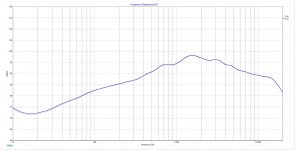
Take note that I have included my spliced in woofer and port summed response from PCD7, but also included the raw measurements of each if you want to splice them yourselves. My splice was done using -6.8 db port level reduction.
It looks like I will need to add the remaining files in another post.
Best,
Rich
Attachments
Ok,
I'm back again with the missing files. I had to zip files to upload these. I kept getting an upload error saying files were to large for the select type. Anyway, here is last 4 to go with those from prior post.
Best,
Rich
I'm back again with the missing files. I had to zip files to upload these. I kept getting an upload error saying files were to large for the select type. Anyway, here is last 4 to go with those from prior post.
Best,
Rich
Attachments
Don't sweat the 87db it was just a starting point, and as jReave has pointed out, starting with full 6db means you have the option of unwinding inductors to tune. An aspect I had not considered ")
Also you might want to check out this thread Moving Mic Measurement (again as jReave suggested some in room measurements, I find this method gives good results (though it is a bit tricky to get it right))
This will give a good idea what the response is like in your room, you can place the speakers where you intend to use them and you will pretty quickly see how your bass is without any compensation. You can compare that to the baffle step adjusted spliced measurement, which will hopefully give an idea as to how much baffle step compensation you are going to need.
The latest splicing looks more like what I would expect for ported 8" though I'm curious about the db level you adjusted the port by. From memory there is a formula that you need to apply based on relative area of the port compared to the area of the woofer, but I can't remember off the top of my head, was the db value you posted the answer from that formula?
Gotta go, will have a closer look later.
Also you might want to check out this thread Moving Mic Measurement (again as jReave suggested some in room measurements, I find this method gives good results (though it is a bit tricky to get it right))
This will give a good idea what the response is like in your room, you can place the speakers where you intend to use them and you will pretty quickly see how your bass is without any compensation. You can compare that to the baffle step adjusted spliced measurement, which will hopefully give an idea as to how much baffle step compensation you are going to need.
The latest splicing looks more like what I would expect for ported 8"
though I'm curious about the db level you adjusted the port by. From memory there is a formula that you need to apply based on relative area of the port compared to the area of the woofer, but I can't remember off the top of my head, was the db value you posted the answer from that formula? Gotta go, will have a closer look later.
Hi Guys,
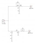
Here is another Xover version to consider. I added the tank to L1 as suggested. Also, the resonant filter for tweeter won't cost to much, but if guys say lose it (its gone). I attached system z with that filter and without for comparing. Hopefully, when the dust settles this one is a keeper because it will only cost about $40.00 to purchase the necessary components for both speakers. I bought a coil and cap tester recently so I now have the ability to unwind coils to achieve exact values. In testing coils and caps I already have on hand it appears rather accurate. It probably will pay for itself on this build alone.
Best,
Rich
Here is another Xover version to consider. I added the tank to L1 as suggested. Also, the resonant filter for tweeter won't cost to much, but if guys say lose it (its gone).
I attached system z with that filter and without for comparing. Hopefully, when the dust settles this one is a keeper because it will only cost about $40.00 to purchase the necessary components for both speakers. I bought a coil and cap tester recently so I now have the ability to unwind coils to achieve exact values. In testing coils and caps I already have on hand it appears rather accurate. It probably will pay for itself on this build alone.Best,
Rich
Attachments
Thanks Tony,
I will check out the thread you referenced. This was taken from Jeff Bagby's white paper. "Lower the port by 20 Log (Port Diameter / Cone Diameter). So, for our 6.5” woofer, with its 5” cone area, working with a 2” port, the port output will need to be lowered by 20 Log (2 / 5) = -7.96 dB, or roughly 8 decibels". In my case it is a 3" diameter port and 6.5" diameter cone area. If I did the math correctly it yields -6.8 db.
Best Regards,
Rich
I've just had a play with a few of your measurements in speaker workshop, wanted to do a sanity check.
I tried to get a match by dialing in z offset but it wasn't too successful. I may need to put into PCD or xsim with actual driver vertical and horizontal offsets to get a good match.
But it lead me to a question. Were the individual driver measurements done on axis with each driver, or with the mic in the same location for both drivers (and the combined measurement)? From memory Jeff's method for getting z offset has all measurements taken with the mic in the same position.
However that has me wondering about subsequent measurements. Should they be done on axis with the individual drivers. I think that is what I did when I did my active crossover especially because there was a big offset vertically between my woofers and my MTM's.
Maybe it doesn't matter provided you get the offsets set up so that the sim and the measurements match up.
Could you give me your woofer and tweeter offsets so I could try in PCD?
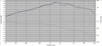
Below is what I got, blue is the actual measurement, black is simulated with 70mm offset on the tweeter (I only have z offset at my disposal in speaker workshop)
Tony.
I tried to get a match by dialing in z offset but it wasn't too successful. I may need to put into PCD or xsim with actual driver vertical and horizontal offsets to get a good match.
But it lead me to a question. Were the individual driver measurements done on axis with each driver, or with the mic in the same location for both drivers (and the combined measurement)? From memory Jeff's method for getting z offset has all measurements taken with the mic in the same position.
However that has me wondering about subsequent measurements. Should they be done on axis with the individual drivers. I think that is what I did when I did my active crossover especially because there was a big offset vertically between my woofers and my MTM's.
Maybe it doesn't matter provided you get the offsets set up so that the sim and the measurements match up.
Could you give me your woofer and tweeter offsets so I could try in PCD?
Below is what I got, blue is the actual measurement, black is simulated with 70mm offset on the tweeter (I only have z offset at my disposal in speaker workshop)
Tony.
Attachments
Hi Tony,
Thanks for taking the time to go through and making sure I'm on the right track. I used Xsim to dial in my offset and it worked out to be .66 in. to get lines to match up rather well. Here is my driver locations:
Woofer: located 18 inches from bottom of cab.
Tweeter located 9.75 inches from bottom of cab.
The baffle dimensions are 25 inches tall and 12 inches wide. They will be placed on 13 inch stands. You probably noticed from earlier photo of my measurement setup that the tweeter is mounted in waveguide below the woofer. Oh, BTW I took measurements on woofer axis and did not change mic location at all when capturing the combined measurement of both. Hopefully, I have provided you with all the necessary information.
Have a Great Day,
Rich
Thanks for taking the time to go through and making sure I'm on the right track.
I used Xsim to dial in my offset and it worked out to be .66 in. to get lines to match up rather well. Here is my driver locations:Woofer: located 18 inches from bottom of cab.
Tweeter located 9.75 inches from bottom of cab.
The baffle dimensions are 25 inches tall and 12 inches wide. They will be placed on 13 inch stands. You probably noticed from earlier photo of my measurement setup that the tweeter is mounted in waveguide below the woofer. Oh, BTW I took measurements on woofer axis and did not change mic location at all when capturing the combined measurement of both. Hopefully, I have provided you with all the necessary information.
Have a Great Day,
Rich
Hi Tony,
I failed to mention in prior post the .66 inch mod delay was for woofer z offset. My coffee is finally kicking in. I have attached screen shot in Xsim of what my overlays look like. The grey line is the imported woofer and tweeter combined response. At closer look .63 inch looks to overlay better but probably won't change things much.
Best,
Rich
I failed to mention in prior post the .66 inch mod delay was for woofer z offset. My coffee is finally kicking in.
I have attached screen shot in Xsim of what my overlays look like. The grey line is the imported woofer and tweeter combined response. At closer look .63 inch looks to overlay better but probably won't change things much.Best,
Rich
Attachments
Last edited:
One last thing about the measurements. Although your graphs say 1/48th smoothing, they look like more than that. ?? Not sure if you may be missing out on any finer details.
Otherwise, measurements appear to be well dialed in and now it's just the little matter of the xo.
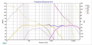
One thing to do in XSim on your Frequency Response graph is to move the vertical center down (in 'Scale') so that you can see more of the frequency range below your summed response. So for example, I can't really see if that .47uF cap is in the right place as it doesn't look like it's really done that much to the response around 3kHz. I suspect that value might be a little small. Try maybe twice as big and try a resistor in series with it as well. That cone breakup with that woofer isn't all that egregious but I would still attack it and lower it some more probably centered at about 3300 -3500Hz.
It looks like you are going LR4 on the xo which is a good choice in this application. I suspect that you can hit that target curve on the woofer with just 2nd order electric but without running the sim myself, I'm not sure if that will get good phase alignment. As it is, in all of your versions, phase has been lined up extremely well, so well done on that.
To be thorough, one last thing I might do is also run the sim in PCD for the express purpose of looking at the power response in the xo region. The danger with an 8" in a 2-way is for a dip in the off-axis response in the xo region and XSim doesn't show this. If your sim in PCD shows this to be the case, you might try to compensate for this by making sure the on-axis response in that region does not also have a corresponding dip and is at least flat if not perhaps just a tad "hilly". You may need to increase the tweeter response in that region to do so but with a waveguide that should be possible I would think.
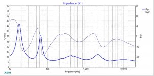
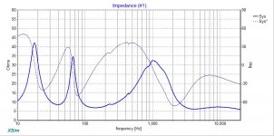
Re the impedance compensation filter on the tweeter, I would keep it not for the purposes of flattening your impedance (which isn't a bad thing but also isn't something that most modern amplifiers require), but instead to make sure that the impedance resonance stays as low as possible in terms of SPL. Also I'm not sure if it makes a difference but I thought that usually that filter goes right before the driver. Maybe I'm misremembering.
Otherwise, measurements appear to be well dialed in and now it's just the little matter of the xo.
One thing to do in XSim on your Frequency Response graph is to move the vertical center down (in 'Scale') so that you can see more of the frequency range below your summed response. So for example, I can't really see if that .47uF cap is in the right place as it doesn't look like it's really done that much to the response around 3kHz. I suspect that value might be a little small. Try maybe twice as big and try a resistor in series with it as well. That cone breakup with that woofer isn't all that egregious but I would still attack it and lower it some more probably centered at about 3300 -3500Hz.
It looks like you are going LR4 on the xo which is a good choice in this application. I suspect that you can hit that target curve on the woofer with just 2nd order electric but without running the sim myself, I'm not sure if that will get good phase alignment. As it is, in all of your versions, phase has been lined up extremely well, so well done on that.
To be thorough, one last thing I might do is also run the sim in PCD for the express purpose of looking at the power response in the xo region. The danger with an 8" in a 2-way is for a dip in the off-axis response in the xo region and XSim doesn't show this. If your sim in PCD shows this to be the case, you might try to compensate for this by making sure the on-axis response in that region does not also have a corresponding dip and is at least flat if not perhaps just a tad "hilly". You may need to increase the tweeter response in that region to do so but with a waveguide that should be possible I would think.
Re the impedance compensation filter on the tweeter, I would keep it not for the purposes of flattening your impedance (which isn't a bad thing but also isn't something that most modern amplifiers require), but instead to make sure that the impedance resonance stays as low as possible in terms of SPL. Also I'm not sure if it makes a difference but I thought that usually that filter goes right before the driver. Maybe I'm misremembering.
Hi jReave,
Thanks for taking the time to share your expertise! I will try the the suggestions that you mentioned regarding the Xover. It will probably be Tuesday morning before I'm able to try out the suggestions you offered. I'm away on a work related seminar. Rather be home working on finishing this project but duty calls I suppose.
Re: REW, I'm still learning its capabilities and setup methods. So far, I have just tried the settings Draki recommended in post #3. So, if you have any tips to share on REW settings to achieve the most realistic measurements then I'm all ears. Later this week I'll be taking measurements of the dual woofer 3 ways, so that would be good time to apply any new settings or techniques that you suggest.
Best Regards,
Rich
Thanks for taking the time to share your expertise! I will try the the suggestions that you mentioned regarding the Xover. It will probably be Tuesday morning before I'm able to try out the suggestions you offered. I'm away on a work related seminar. Rather be home working on finishing this project but duty calls I suppose.
Re: REW, I'm still learning its capabilities and setup methods. So far, I have just tried the settings Draki recommended in post #3. So, if you have any tips to share on REW settings to achieve the most realistic measurements then I'm all ears.
Later this week I'll be taking measurements of the dual woofer 3 ways, so that would be good time to apply any new settings or techniques that you suggest. Best Regards,
Rich
Yes, in REW the smoothing in under the "Graph" drop down menu or you can set it universally in the Preferences -> Analysis window.
My confusion (also known as my normal state) is that 1/48th or even 1/24th should provide plenty of detail but your measurement graphs look more like about 1/6th or even 1/3rd. So I can't figure it out. 
My confusion (also known as my normal state
) is that 1/48th or even 1/24th should provide plenty of detail but your measurement graphs look more like about 1/6th or even 1/3rd. So I can't figure it out. One way to find out. Change it back one good thing with rew is that nothing is permanent the original raw measurement should always be available. Just the display of it is changed.
I'm not familiar at all with the gated measurements with rew though so really no help there.
Tony.
one good thing with rew is that nothing is permanent the original raw measurement should always be available. Just the display of it is changed. I'm not familiar at all with the gated measurements with rew though so really no help there.
Tony.
Hi jReave,
I have been changing 15 cycles to 6 in IR window as Draki suggested. Could that be adding to much smoothing? Just trying to help solve the mystery.
Best,
Rich
IME, using 6 cycles, 1/48 and Frequency Dependent Window is good enough and very much usable for a x/o design (I must state that I use LspCAD's Just Measure, and REW as a backup, reality check).
Now, if you feel that "good enough" is not enough you can of course use more resolute window (eg 15) but you might be overwhelmed by too many details. Start and design with 6, check with 15. Whatever works for you.
At the peril of stating the obvious: all the measurements in REW, once saved, can be presented at many different ways - using different settings for the gate time, with or without FDW, cycles width, graph smoothing... So you can look (and export, for a xo design etc) one same measurement differently at any time, no need to make new ones.
- Status
- This old topic is closed. If you want to reopen this topic, contact a moderator using the "Report Post" button.
- Home
- Loudspeakers
- Multi-Way
- Need help interpreting measurements