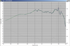
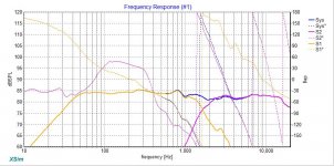
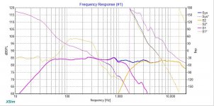
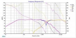
Thanks Draki, I did a quick comparison of a measurement of an SB accoustics 4" I did a while back. All gated at 4ms but without the Frequency dependent window, then with 15 cycles FDW and 6 cycles FDW result is below:
Black is no FDW
Blue is with 15 cycles
Green is with 6 cycles
Tony.
Black is no FDW
Blue is with 15 cycles
Green is with 6 cycles
Tony.
Attachments
Hi Rich, your overlay looks very good. I'm unable to reproduce it though. I must be missing something or doing something stupid  One thing I didn't get from you is your measurement distance. I've assumed 1M but going up and down a bit didn't help. I should have enough to get a valid result in PCD but what I'm getting is worse than what I got in speakerworkshop
I think I need to sleep on it
Tony.
One thing I didn't get from you is your measurement distance. I've assumed 1M but going up and down a bit didn't help. I should have enough to get a valid result in PCD but what I'm getting is worse than what I got in speakerworkshop I think I need to sleep on it
Tony.
Tony, could be the Y-coordinates were wrong and/or the convention of writing Z-offset is causing it. Tried the PCD and it worked with 1m mic away (correct?). In XSim the delay goes to woofer with +0.66 inch and in PCD the tweeter gets the same delay as -0.0167 m.
@Rich, I was watching phase response of your woofer far field and appeared to me as if it did not correlate with RM's calculation of it, and the tweeter was fine. Nothing of much gravity.
@Rich, I was watching phase response of your woofer far field and appeared to me as if it did not correlate with RM's calculation of it, and the tweeter was fine. Nothing of much gravity.
Last edited:
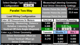
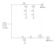
OK here is what I put in, could you please point out where I've made a really dumb mistake I'm really not seeing it, and it is really starting to bug me!!
I calculated Y offset assuming that the zero line is centre of woofer (as measurement was on axis with the woofer) , and tweeter below that 18" - 9.5" = 8.5" so negative. Woofer z offset as negative as behind the tweeter.
Tony.
I'm really not seeing it, and it is really starting to bug me!! I calculated Y offset assuming that the zero line is centre of woofer (as measurement was on axis with the woofer) , and tweeter below that 18" - 9.5" = 8.5" so negative. Woofer z offset as negative as behind the tweeter.
Tony.
Attachments
Right, yesterday evening I've had exactly the same issues with these figures.
edit: appeared you used Rich's woofer response with "suspicious" phase. I recalculated it with RM and it is very much different than original.
edit: appeared you used Rich's woofer response with "suspicious" phase. I recalculated it with RM and it is very much different than original.
Attachments
Last edited:
What Tony entered into PCD is formally correct with v7 (with v6 z offset was reversed, i.e. positive values for voice coil behind the speaker baffle). Note that y offset in this case for the tweeter can also be positive, as the situation is specular. However z offset from PCD is not equal to the delay from XSim. The XSim delay is simply the path difference between two drivers to the mic, whereas the z offset is only one of the elements that combine to form the path difference.
If 1.67cm is what is entered into XSim for the woofer, then the correct value for z offset for the woofer is -3.85 cm (together with the 21 cm y offset for the tweeter).
Ralf
If 1.67cm is what is entered into XSim for the woofer, then the correct value for z offset for the woofer is -3.85 cm (together with the 21 cm y offset for the tweeter).
Ralf
Hi Lojzek,
I'm away from my computer today and not able to double check any phase errors that you mentioned. I may be able to shed some light though. All the files that were attached in the above posts were raw measurements that included unwrapped phase in REW without minphase extracted. Now the screenshots of Xsim schematics include files with minphase that has been extracted in Response blender when merging farfield and near fields or RM in the case of the tweeter. Hope that information adds some clarity. Please let me know if there is something I have overlooked.
Tony,
I feel bad this exercise has turned into a headache rather then something fun. Hopefully, as I type this you have the offsets overlayed correctly. Oh, mic distance for the farfield measurements was 27 inches. I'm still confused why in Xsim there would be any issues aligning offsets. I will check back in periodically through the day if you have anymore questions.
Best,
Rich
I'm away from my computer today and not able to double check any phase errors that you mentioned. I may be able to shed some light though. All the files that were attached in the above posts were raw measurements that included unwrapped phase in REW without minphase extracted. Now the screenshots of Xsim schematics include files with minphase that has been extracted in Response blender when merging farfield and near fields or RM in the case of the tweeter. Hope that information adds some clarity.
Please let me know if there is something I have overlooked.Tony,
I feel bad this exercise has turned into a headache rather then something fun. Hopefully, as I type this you have the offsets overlayed correctly. Oh, mic distance for the farfield measurements was 27 inches. I'm still confused why in Xsim there would be any issues aligning offsets.
I will check back in periodically through the day if you have anymore questions.Best,
Rich
Hi Wish! Boring all day seminar but required to keep my Pesticide license. I'm required by the State of Idaho to have 15 hours continued education every 2 years. So here I am, dreading the start of an incredibly long day. Rather be working on my speaker projects.
Best,
Rich
Best,
Rich
Don't feel bad Rich, I assumed that the measurements had already had minimum phase extracted! Now I know why I am having the issue
That's the reason for doing a sanity check, to make sure what I think I'm working with is actually what I'm working with The old addage, never assume, it makes an *** out of u and me!
Tony.
Now I know why I am having the issue That's the reason for doing a sanity check, to make sure what I think I'm working with is actually what I'm working with
The old addage, never assume, it makes an *** out of u and me! Tony.
Hi Tony,
That makes me feel a lot better that you are not upset with the whole process. When I'm able to resume working on this tomorrow morning, my first order of business will be to extract minphase from all my farfield measurements. I'm really interested in what settings you arrive at in PCD7 for offsets. Could you post your findings? Even though most of my work will be in Xsim, I will still use PCD7 to see power response as jReave suggested.
Best Regards,
Rich
That makes me feel a lot better that you are not upset with the whole process.
When I'm able to resume working on this tomorrow morning, my first order of business will be to extract minphase from all my farfield measurements. I'm really interested in what settings you arrive at in PCD7 for offsets. Could you post your findings? Even though most of my work will be in Xsim, I will still use PCD7 to see power response as jReave suggested.Best Regards,
Rich
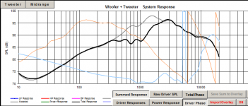
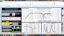
Using FRD's with miimum phase works a lot better
I would say that your waveguide combined with this woofer has given you almost perfect time alignment (at least at that measuring mic position).
I didn't have to use any z offset at all. + or - 1mm makes small differences but I think overall it is best left at zero in PCD. See below:
Also works much better in speaker workshop, but not quite as good a match as PCD.
Tony.
Attachments
Hi Tony,
That is Awesome! I'm glad that the file mystery is solved. I will go through my files tomorrow morning and extract minphase as well. This has been quite the learning experience for me. I'm glad that I sought out second opinion before proceeding with purchase of Xover parts because there probably will need to be changes made to design once correct offsets are included.. While I'm going through my files tomorrow I will look to experiment with smoothing or lack thereof in REW.
Much Thanks!
Rich
That is Awesome!
I'm glad that the file mystery is solved. I will go through my files tomorrow morning and extract minphase as well. This has been quite the learning experience for me. I'm glad that I sought out second opinion before proceeding with purchase of Xover parts because there probably will need to be changes made to design once correct offsets are included.. While I'm going through my files tomorrow I will look to experiment with smoothing or lack thereof in REW.Much Thanks!
Rich
Hello Guys,
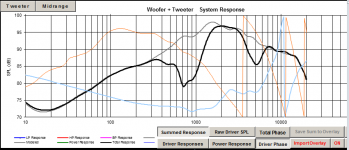
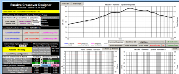
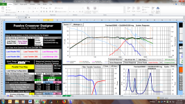
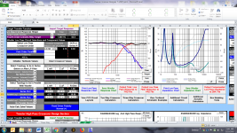
I'm back once again with another Xover version for consideration. This with corrected phase as pointed out by Lojzek in prior posts. It was an eye opener as how greatly phase effects offsets. I had to remove all mod delay from woofer (.66 inches) and apply 1.22 inches to tweeter in Xsim to get overlays to align. I'm pretty certain things are correct now.
Take note the slight differences in frequency response between Xsim and PCD7. I think the differences could be that in PCD7 I changed the listening distance to 2.00 meters and Xsim it is based on .686 meters (true mic measurement distance). I could have imported a summed response from PCD into Xsim with 2.00 meter distance but have not done that as of yet. I probably will be using PCD7 to make any minor design changes and use Xsim to print a nice schematic to build the Xover. Also, I have attached woofer and tweeter sections from PCD7. Please let me know if it does not match to Xsim schematic in regards to parts layout.
I really appreciate the excellent advice and direction that has been offered in this thread!
Thanks To All,
Rich
I'm back once again with another Xover version for consideration.
This with corrected phase as pointed out by Lojzek in prior posts. It was an eye opener as how greatly phase effects offsets. I had to remove all mod delay from woofer (.66 inches) and apply 1.22 inches to tweeter in Xsim to get overlays to align. I'm pretty certain things are correct now.Take note the slight differences in frequency response between Xsim and PCD7. I think the differences could be that in PCD7 I changed the listening distance to 2.00 meters and Xsim it is based on .686 meters (true mic measurement distance). I could have imported a summed response from PCD into Xsim with 2.00 meter distance but have not done that as of yet. I probably will be using PCD7 to make any minor design changes and use Xsim to print a nice schematic to build the Xover. Also, I have attached woofer and tweeter sections from PCD7. Please let me know if it does not match to Xsim schematic in regards to parts layout.
I really appreciate the excellent advice and direction that has been offered in this thread!
Thanks To All,
Rich
Attachments
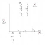
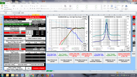
And one more Xsim version....
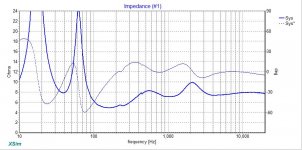
This version has not been changed much from prior post but does reflect an offset adjustment. I took a summed response from PCD7 at 2 meter listening distance and imported it into Xsim. It required reducing tweeter mod delay from 1.22 to .44 inches to align overlays. You can see now that both PCD7 version and Xsim agree. Also, I removed resonant compensation filter from schematic. It probably is not altogether necessary other then to flatten impedance some.
Guys, let me know if I can go to press with this version. I would like to get a Parts Express order together and coming my way.
Best,
Rich
This version has not been changed much from prior post but does reflect an offset adjustment. I took a summed response from PCD7 at 2 meter listening distance and imported it into Xsim. It required reducing tweeter mod delay from 1.22 to .44 inches to align overlays. You can see now that both PCD7 version and Xsim agree. Also, I removed resonant compensation filter from schematic. It probably is not altogether necessary other then to flatten impedance some.
Guys, let me know if I can go to press with this version.
I would like to get a Parts Express order together and coming my way.Best,
Rich
Attachments
- Status
- This old topic is closed. If you want to reopen this topic, contact a moderator using the "Report Post" button.
- Home
- Loudspeakers
- Multi-Way
- Need help interpreting measurements