I used no xovers in the sim... I would just add ~250hz 4th order LR HPF to both channels, as they seem to compliment each other. Furthermore I have an EQ available.
I know that it's just an assumption and I wanted to update the Horn over time; meaning that certain components can stay (for example the throat adapter). Also you can easily change the Mid ports without having to rebuild the whole horn.
But what can go wrong in a Horn like this? Do you have any experiences?
And to be honest, the horn doesn't need to be perfect by any means... I plan on using one with 4 MTH-30s loaded with cheapo drivers for free party outdoor applications... The whole system won't cost more than 600€, which is quite awesome for the performance it offers...
The DE250 parameters are from an akabak script I found. They seem to work quite good, but once I get the Horn measured, I will compare the results.
I can't thank you enough for all your advice and patience!")
I know that it's just an assumption and I wanted to update the Horn over time; meaning that certain components can stay (for example the throat adapter). Also you can easily change the Mid ports without having to rebuild the whole horn.
But what can go wrong in a Horn like this? Do you have any experiences?
And to be honest, the horn doesn't need to be perfect by any means... I plan on using one with 4 MTH-30s loaded with cheapo drivers for free party outdoor applications... The whole system won't cost more than 600€, which is quite awesome for the performance it offers...
The DE250 parameters are from an akabak script I found. They seem to work quite good, but once I get the Horn measured, I will compare the results.
I can't thank you enough for all your advice and patience!
little update:
I found some other tsp's for the 0410MR by accident: Red Spade Audio: Akabak vs Hornresp vs Real measurements They look to be very accurate...
The sim wasn't as flat anymore but had more low end. I just had to increase vtc a bit and got an even better result than v1.3 ...
I found some other tsp's for the 0410MR by accident: Red Spade Audio: Akabak vs Hornresp vs Real measurements They look to be very accurate...
The sim wasn't as flat anymore but had more low end. I just had to increase vtc a bit and got an even better result than v1.3 ...
Hi,
my supplier sent me a message, that celestion can't ship their order for some reason. I'm really mad now, as I ordered like 3months ago.
They stated, that they could give me the 5" or the 6", which they have in stock, for the same price, if it would fit my needs.
As there are no TSP's provided by Celestion, could you give me some sort of educated guess, because I'm not able to.
Thanks in advance!
Are you looking for an alternate to the Celestion closed back mids? If this is indeed a 300 Hz and up 2-way design, then there is no need for closed back because there won't be any woofers in the same box. My Synergy played 300 Hz and up from 2 pairs of Faital 4FE35, although the Faitals could extend down to 150 Hz if needed. (use only two if you don't need the extension) These would be an especially good choice for you because the Faitals are high Q and don't seem to be sensitive to box volume - ie. you wouldn't need to complicate your box with separate chambers for the mids.
Hi,
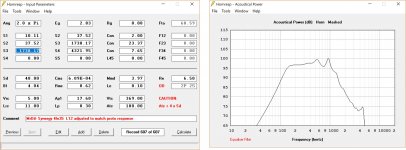
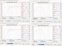
the 4fe35 looks good on paper, but my simulation isn't that great:

Grey: 7cm^2 port
Red: 10cm^2 port
Both: 10litres vrc, 60cm^3 vtc, wired in parallel
I would like to have a higher sensitivity on the mid's.
Is there anything I can do?
also: Is the dip on the HF driver from the ports really that pronounced?
Thanks!
the 4fe35 looks good on paper, but my simulation isn't that great:
Grey: 7cm^2 port
Red: 10cm^2 port
Both: 10litres vrc, 60cm^3 vtc, wired in parallel
I would like to have a higher sensitivity on the mid's.
Is there anything I can do?
also: Is the dip on the HF driver from the ports really that pronounced?
Thanks!
There are lots of things you can do but first lets debug your model. You've only shown half; I also need to see the MEH part that shows the mid parameters.
But from what I can see.... L12 is impractically short and doesn't need to be that short and the mid may like it better ported further down the horn.
94 db is about what I would expect from two 4FE35s in parallel without horn or corner gain. I don't see horn gain coming in in your model, at least not like I expect. The jump in output between 1 and 2 Khz could be impedance mismatch - 8 ohm CD vs 4 ohm or 16 ohms for the two mids depending on how they are wired.
and I think the notch will vary or can be tuned away by modelling delay between CD and mid.
I will attach my sim model for the 4FE35s as offset drivers on my synergy.

The L12 in my model started out as 4 cm for the horn and 6 cm or so for the acoustic path length within the CD, back to where sound reflects from. You can model as I did by increasing the L12 or as a throat chamber. But then I reduced that number so the model matched the measurement, at least as to reflection null location.
You see in the grey (unequealized trace) a horn mouth reflection null just under 400 hz and then horn gain beginning as response rises above that frequency. My horn is not that much bigger than yours. I would expect horn gain at least by 600 Hz or 700 hz.
Hope that helps
But from what I can see.... L12 is impractically short and doesn't need to be that short and the mid may like it better ported further down the horn.
94 db is about what I would expect from two 4FE35s in parallel without horn or corner gain. I don't see horn gain coming in in your model, at least not like I expect. The jump in output between 1 and 2 Khz could be impedance mismatch - 8 ohm CD vs 4 ohm or 16 ohms for the two mids depending on how they are wired.
and I think the notch will vary or can be tuned away by modelling delay between CD and mid.
I will attach my sim model for the 4FE35s as offset drivers on my synergy.
The L12 in my model started out as 4 cm for the horn and 6 cm or so for the acoustic path length within the CD, back to where sound reflects from. You can model as I did by increasing the L12 or as a throat chamber. But then I reduced that number so the model matched the measurement, at least as to reflection null location.
You see in the grey (unequealized trace) a horn mouth reflection null just under 400 hz and then horn gain beginning as response rises above that frequency. My horn is not that much bigger than yours. I would expect horn gain at least by 600 Hz or 700 hz.
Hope that helps
I take part of that back. I'm not used to looking at MEH sims; I usually just sim the mids as I dont' trust my model for the CD.
LF to HF response levels probably just sensitivity difference.
I expect and see more midrange response ripple in your horn as it has reflections from both the mouth and the break between primary and secondary flares so that much makes sense but I'm surprised there is no response level increase following the rise in acoustic impedance as the horn gains pattern control.
Is the freq resp your showing the composite of the CD and the mid as I assumed or just the mid as implied by the text boxes at the bottom of the screenshot.?
If your freq
A little bit rushed last night.
Here are four of the 4FE drivers on your horn with a little optimization but really should redo with L12 at least 4 cm. In fact, you should try to see how far down the horn you can push the mid ports and still make an XO at 1 Khz or so. With 1.4" exit driver supporting 650 Hz ? XO you could go a bit lower in frequency and further down the horn.
here is a nicer response at L12=6cm.
Some of those 6cm will be cd mounting plate and internal acoustic path in the CD
Attachments
Hi nc535,
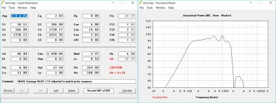
although your sims look really nice, I would like to stay with two drivers.
Here is what I accomplished:

There is only the sensitivity problem left now, which i think I'll just fix by turning the Mid's up, although I would waste the power capabilities of the DE250 (around half of it).
What do you think?
Thanks a lot!
although your sims look really nice, I would like to stay with two drivers.
Here is what I accomplished:
There is only the sensitivity problem left now, which i think I'll just fix by turning the Mid's up, although I would waste the power capabilities of the DE250 (around half of it).
What do you think?
Thanks a lot!
That is looking good. I agree, no need for 4 drivers, that is just what I had on hand for quick changes to reflect your horn.
Do you really need a 2 Khz XO to the CD? If not, I would push the mids out further but only to the point where the horn circumference at the entry point equals 1 wavelength at the XO
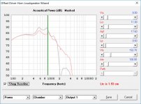
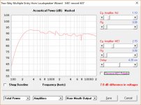
I see your Lp is now up to 1.5 cm and you have a nearly brickwall fall off at the high end of the mids. You probably have noticed by now that Lp, Ap1, and Vtc interact to change the slope of the bandpass response fall off at the high end of the mds. I get a similar thing when I take my sim and reduce it to 2 mids, reducing the Vtc along with it. That is the grey trace below. The red trace results from reducing the port length to .6 cm (meaning hole will be frustrumized) and then tuning the Vtc from half what I had with 4 drivers up to 193cc. Which results in better XO? I'm not sure but I went with the gradual slope myself because I didn't want to brickwall the CD.
But we aren't done yet. First EQ, including 2nd order HPF and LPF XO filters, turn power up to max (120W) and then check peak particle velocity at throat port exit. This gives 110 db sound power which should be enough in home. Excursion is slightly below Xmax. Peak particle velocity is 8.5 m/s, which means we could get by with perhaps as much as 50% smaller holes.
So if this were my project, I would go back through the loop again re-optimizing around smaller hole size.
So good luck. I think you are on the right track.
Do you really need a 2 Khz XO to the CD? If not, I would push the mids out further but only to the point where the horn circumference at the entry point equals 1 wavelength at the XO
I see your Lp is now up to 1.5 cm and you have a nearly brickwall fall off at the high end of the mids. You probably have noticed by now that Lp, Ap1, and Vtc interact to change the slope of the bandpass response fall off at the high end of the mds. I get a similar thing when I take my sim and reduce it to 2 mids, reducing the Vtc along with it. That is the grey trace below. The red trace results from reducing the port length to .6 cm (meaning hole will be frustrumized) and then tuning the Vtc from half what I had with 4 drivers up to 193cc. Which results in better XO? I'm not sure but I went with the gradual slope myself because I didn't want to brickwall the CD.
But we aren't done yet. First EQ, including 2nd order HPF and LPF XO filters, turn power up to max (120W) and then check peak particle velocity at throat port exit. This gives 110 db sound power which should be enough in home. Excursion is slightly below Xmax. Peak particle velocity is 8.5 m/s, which means we could get by with perhaps as much as 50% smaller holes.
So if this were my project, I would go back through the loop again re-optimizing around smaller hole size.
So good luck. I think you are on the right track.
Attachments

two ways to get more output between 400 & 500, which you probably won't like, are
1. enlarge the horn so pattern control and horn gain extend down to 400 Hz
2. add two more mids
or just equalize it, its just a 3 db dip
That dip is probably due to a mouth reflection. Your horn's impulse spectrogram (tools menu in power screen) does show a bulge in that frequency range at ~1.5 ms delay. Implementing roundovers instead of a secondary flare should dramatically reduce mouth reflections.
Hi,
I've decided to go with 4 drivers, because of the power mismatch. However it didn't fix the dip and enlarging L13 didn't help either; I'm just going to eq it.
other than that it looks pretty good to me.
Have to sim particle velocity and xmax now.

And just when I wanted to order, the DE250 was out of stock...
It should be there soon so I have some time to tweek the design.
I've decided to go with 4 drivers, because of the power mismatch. However it didn't fix the dip and enlarging L13 didn't help either; I'm just going to eq it.
other than that it looks pretty good to me.
Have to sim particle velocity and xmax now.
And just when I wanted to order, the DE250 was out of stock...
It should be there soon so I have some time to tweek the design.
I created ME1 and Nd records here and tried to replicate your results with some but not total success. The 2 khz XO is much higher than what I would have chosen based on simulations of the mids as offset drivers in a normal simulation not using the multiple entry wizard. I posted about this, with an explanation for the difference in the HornResp thread in the subwoofer forum.
Basically, the notch in the leading edge of the CD's power1 response leads one to believe the mid-CD XO needs to be at a much higher frequency than one would expect looking at a simulation that ignores the mid entry ports. I don't believe those notches show up in an SPL measurement on or close to on axis and thus they should be ignored when judging where the XO should be. Check the circumference of the horn at the mid entry ports. That should be less than a wavelength at your XO for point source summation.
Basically, the notch in the leading edge of the CD's power1 response leads one to believe the mid-CD XO needs to be at a much higher frequency than one would expect looking at a simulation that ignores the mid entry ports. I don't believe those notches show up in an SPL measurement on or close to on axis and thus they should be ignored when judging where the XO should be. Check the circumference of the horn at the mid entry ports. That should be less than a wavelength at your XO for point source summation.
David McBean told me the CD notch was due to the mid ports acting as Helmholtz resonantors. Optimizing port length and area allowed me to get it up out of the XO transition region. That and EQ produced the attached results. Its safe to ignore that notch because it won't show up in your near axis measurements
In addition to the port tuning, I removed your throat chamber because it seemed to be hurting your simulated CD response. Instead I extended the L12 by the length of the chamber. If you look at the schematics, you see a discontinuity at the TC that isn't in the extended throat version. If you implement matching CD exit angle, you won't have a discontinuity at the throat and so that is the way you should simulate.
The lower left end screenshot compares CD response with and without the throat chamber. Its much smoother without the TC and the ripples there are due to mouth reflections. All the other frequency responses are post EQ and I could have used a couple of additional PEQs. The XO is at 1200 Hz 4th order filters, where many have been happy with the DE250 and its clones.
I decided I should show you my EQ terms but when I went back to HR I found they had changed and I had to redo the EQ. Of course it came out differently this time but here its is. I like this one better as it rises slowly towards the bass and is relatively flat out to 20 Khz
Attachments
I forgot to press POST an hour ago. Those screen shots have my port length and area.
5000 is in the ballpark for pink fluffy fiberglass insulation. I don't know why I included it in the model. It came from another model I copied from "JLH" several years ago and its probably just there to tune the model or mask some resonance artifacts. Its presence in the model is not a suggestion to open up your CD and stuff fiberglass in the chamber.
Sorry I thought my port size and length were in the other pics but I see I left that one off. Port area was 19.2 cm2 and port length was .7 cm
Jack
Hi Jack,
I'm done with my final exams for this year now so I have plenty of time to work on this project. I decided to go with 4 drivers.
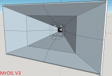
I have overthought the Hornresp-model (throat) and this is what I came up with:

I think, that this model is closest to reality. Before I had S1 in the middle of the exit angle matching.
I am working on the Mid's now.
One question though:
Is ATC the sum of all 4 drivers? (It is with Vtc and Vrc)
I'm done with my final exams for this year now so I have plenty of time to work on this project. I decided to go with 4 drivers.
I have overthought the Hornresp-model (throat) and this is what I came up with:
I think, that this model is closest to reality. Before I had S1 in the middle of the exit angle matching.
I am working on the Mid's now.
One question though:
Is ATC the sum of all 4 drivers? (It is with Vtc and Vrc)
- Status
- This old topic is closed. If you want to reopen this topic, contact a moderator using the "Report Post" button.
- Home
- Loudspeakers
- Multi-Way
- 2-way Unity Horn from 300Hz (some noob questions)