Hello DIY Audio. I some advice regarding my first speaker build as I have been thinking about it to much for to long. The use would be for 2-channel stereo music in a 10x12 room with a 45 watt per channel (8 ohm)/ 90 watt per channel (4 ohm) amplifier without a subwoofer. I prefer a proven design using Seas drivers with assembled crossovers available.
I have narrowed my choices to the Seas Idunn kit at $420/pair or the Seas Bragi at $642/pair, both available from Madisound.
https://www.madisoundspeakerstore.com/2-way-speaker-kits/seas-idunn-2-way-speaker-kit-pair-parts-only/
For the Idunn kit, Madisound offers a standard crossover with Clarity ESA caps. Of the available crossover upgrades Madisound offers, I could afford:
1. Mundorf EVO oil caps in the tweeter circuit (+ $17/pair),
2. Goertz copper foil inductors in the woofer circuit (+ $50/pair).
I would like to which of these upgrades would result in a substantial improvement, if any.
In addition, I have found the Seas Bragi kit ($642/pair) which uses two of the same mid-woofer as the Idunn (MTM?) in similar, but slightly deeper cabinet. No crossover options for this one but it includes a Goetze copper foil inductor in the woofer circuit.
https://www.madisoundspeakerstore.com/new-products/seas-bragi-kit/
Between the Idunn (with or without crossover upgrades) and the Bragi, which would seem like the best choice for moderately loud rock music without requiring a subwoofer?
Thanks in advance for the advice, it is greatly appreciated.")
Rick
I have narrowed my choices to the Seas Idunn kit at $420/pair or the Seas Bragi at $642/pair, both available from Madisound.
https://www.madisoundspeakerstore.com/2-way-speaker-kits/seas-idunn-2-way-speaker-kit-pair-parts-only/
For the Idunn kit, Madisound offers a standard crossover with Clarity ESA caps. Of the available crossover upgrades Madisound offers, I could afford:
1. Mundorf EVO oil caps in the tweeter circuit (+ $17/pair),
2. Goertz copper foil inductors in the woofer circuit (+ $50/pair).
I would like to which of these upgrades would result in a substantial improvement, if any.
In addition, I have found the Seas Bragi kit ($642/pair) which uses two of the same mid-woofer as the Idunn (MTM?) in similar, but slightly deeper cabinet. No crossover options for this one but it includes a Goetze copper foil inductor in the woofer circuit.
https://www.madisoundspeakerstore.com/new-products/seas-bragi-kit/
Between the Idunn (with or without crossover upgrades) and the Bragi, which would seem like the best choice for moderately loud rock music without requiring a subwoofer?
Thanks in advance for the advice, it is greatly appreciated.
Rick
No question. For loudness and authority an MTM like the Bragi wins hands down.
BRAGI
It's more of a PA sound that will suit rock music. You get the reinforcement of multiple bass drivers which projects well.
I really wouldn't fret about crossover quality. It's mostly about the drivers. Save money there, and upgrade later if you feel you must. But as sreten wisely pointed out, expensive coils are a bit of a waste of time when the woofer is a big ferrite coil anyway.
Hello DIY Audio. I some advice regarding my first speaker build as I have been thinking about it to much for to long. The use would be for 2-channel stereo music in a 10x12 room with a 45 watt per channel (8 ohm)/ 90 watt per channel (4 ohm) amplifier without a subwoofer. I prefer a proven design using Seas drivers with assembled crossovers available.
I have narrowed my choices to the Seas Idunn kit at $420/pair or the Seas Bragi at $642/pair, both available from Madisound.
https://www.madisoundspeakerstore.c...seas-idunn-2-way-speaker-kit-pair-parts-only/
For the Idunn kit, Madisound offers a standard crossover with Clarity ESA caps. Of the available crossover upgrades Madisound offers, I could afford:
1. Mundorf EVO oil caps in the tweeter circuit (+ $17/pair),
2. Goertz copper foil inductors in the woofer circuit (+ $50/pair).
I would like to which of these upgrades would result in a substantial improvement, if any.
In addition, I have found the Seas Bragi kit ($642/pair) which uses two of the same mid-woofer as the Idunn (MTM?) in similar, but slightly deeper cabinet. No crossover options for this one but it includes a Goetze copper foil inductor in the woofer circuit.
https://www.madisoundspeakerstore.com/new-products/seas-bragi-kit/
Between the Idunn (with or without crossover upgrades) and the Bragi, which would seem like the best choice for moderately loud rock music without requiring a subwoofer?
Thanks in advance for the advice, it is greatly appreciated.
Rick
I really like the Clarity ESAs and MRs. Mundorf's tend to do magical things to the treble. And by magical, I mean not necessarily realistic. Some like the extra sparkle and fairy sheen, I do not, so I don't think you're loosing much by not having the Mundorf option.
My current monitors use a similar tweeter filter to the Bragi. I've experimented with a 0.1uF Audyn Copper foil cap bypassing both C1 and C2. Bypassing C1 added treble. I did not keep it. Bypassing C2 however added a very nice sweetness to the upper midrange. If you like the Bragi, go ahead and get it as is, but then consider experimenting with a bypass cap later on.
Next, I've never heard either, but I have always liked tweeters with controlled dispersion so in that sense both look like good choices. The one issue with the Bragi is that it has a period between around 100 to 400Hz where the impedance is close to 3 Ohms. Make sure your amps are up to that challenge or the speaker won't sound it's best.
Best,
Erik
Last edited:
Funny how you can fret about tiny differences, and miss some gross errors in the design!
The madisound crossover board is a poor design, placing coils on a ground plane. Also fails to place coil axes at right angles.
That ground plane reduces a 1mH coil to 0.82mH and adds crosstalk. They do other more suitable designs:
https://www.madisoundspeakerstore.com/circuit-boards/
I would add a shunt 22R, or 7.5R plus 0.68uF Zobel to the Bragi's tweeter for high frequency amplifier stability too. The Idunn doesn't need it, having an attenuator.
The madisound crossover board is a poor design, placing coils on a ground plane....
That ground plane reduces a 1mH coil to 0.82mH and adds crosstalk. ...
Um, good thing we no longer use ash trays for crossovers.... Steve, I'm surprised you are drawing such conclusions from that testing. I'm curious how you measured "crosstalk."
I have used this PCB before and the performance of the crossover was exactly as expected, but perhaps because I rotated the big coil.
I am pretty sure I would have seen any changes that gross. I do agree with rotating either of the coils. For me I found it easier to rotate the foil inductor and hot glue+tie it down.
I did note a problem with the male quick-disconnects having poor conductivity to the ground planes due to inadequate soldering so I decided to avoid using them altogether and added pigtails with male connectors to the board directly.
Last edited:
Thanks for all the replies. Would it be advisable for me to assemble my own crossover, assuming the specified components are properly oriented and spaced? I must admit I was a bit intimidated by building a crossover but the more I think about it, it might not be too difficult.
In addition, if I don't limit myself to kits with ready-made crossovers there is a lot more too choose from, such as the ER18DXT. I have seen ER18DXT crossovers assembled on hardboard, which might be good for a beginner (me).
In addition, if I don't limit myself to kits with ready-made crossovers there is a lot more too choose from, such as the ER18DXT. I have seen ER18DXT crossovers assembled on hardboard, which might be good for a beginner (me).
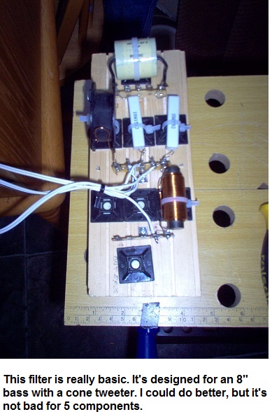
I use a piece of timber for crossovers mostly, being non-conducting, and partly because I don't like covering expensive and reuseable components in glue. Those useful 5 contact thingies are called tagstrip.
FWIW, crosstalk was audible here. The tweeter picked up the 1kHz inductance test tone from the meter via the coils. You could hear it.
FWIW, crosstalk was audible here. The tweeter picked up the 1kHz inductance test tone from the meter via the coils. You could hear it.
Thanks for all the replies. Would it be advisable for me to assemble my own crossover, assuming the specified components are properly oriented and spaced? I must admit I was a bit intimidated by building a crossover but the more I think about it, it might not be too difficult.
In addition, if I don't limit myself to kits with ready-made crossovers there is a lot more too choose from, such as the ER18DXT. I have seen ER18DXT crossovers assembled on hardboard, which might be good for a beginner (me).
Assembly is easy with the right tools:
- A temperature controlled station, I use a more expensive Aoyue than this one, but I really like it.
- The right tip is important. Solder irons usually come with very small tips for PC board work. The caps, coils and power resistors we work with tend to be thick, heat sucking monsters so you'll need a tip more like a Sharpie than a fine pencil.
- Also make sure your solder is thick enough. You can always fold solder to make it thicker, but it's a pain.
- Desolder suction tool (included in the deluxe kit, above)
- Glue gun - Don't rely on solder to keep pieces like 5w resistors attached to a board.
- Wire ties to hold heavier pieces like foil inductors
I use a piece of timber for crossovers mostly, being non-conducting, and partly because I don't like covering expensive and reuseable components in glue. Those useful 5 contact thingies are called tagstrip.
Very nice! And a good cost-saving approach too.
FWIW, crosstalk was audible here. The tweeter picked up the 1kHz inductance test tone from the meter via the coils. You could hear it.
Interesting, but in this particular case the coils were aligned, which is of course a bad thing. I should try some tests like that myself.
Best,
Erik
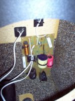
System 7 - what are the square black things under the components on your wood crossover?
Rick
I'm pretty sure they are just wire ties similar to this.
Kind of a brilliant use of them I think.
Best,
Erik
System 7 - what are the square black things under the components on your wood crossover?
Rick
Erik has answered it exactly. Cable ties. Little plastic things with an adhesive pad which sticks them down. The white nylon things are Zip-ties, familiar to the Army for tying up prisoners wrists.
Did we mention that you must tin a new modern tip with solder the first time it heats up? Otherwise it oxidises and is quite ruined.
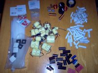
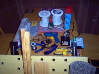
I suppose, since a picture is often worth a thousand words, I should show off some of my other bits and pieces.
I'm a bit short on large value capacitors right now, but have most of the other parts and tools.
It can get to be an expensive hobby. Which, by definition, is an INTERESTING waste of time.
I'm a bit short on large value capacitors right now, but have most of the other parts and tools.
It can get to be an expensive hobby. Which, by definition, is an INTERESTING waste of time.
Attachments
I suppose, since a picture is often worth a thousand words, I should show off some of my other bits and pieces.
I'm a bit short on large value capacitors right now, but have most of the other parts and tools.
It can get to be an expensive hobby. Which, by definition, is an INTERESTING waste of time.
Very nice, but i'm not sure why you like the example on the right, but not the PCB's from madisound.
Best,
Erik
Very nice, but i'm not sure why you like the example on the right, but not the PCB's from madisound.
Best,
Erik
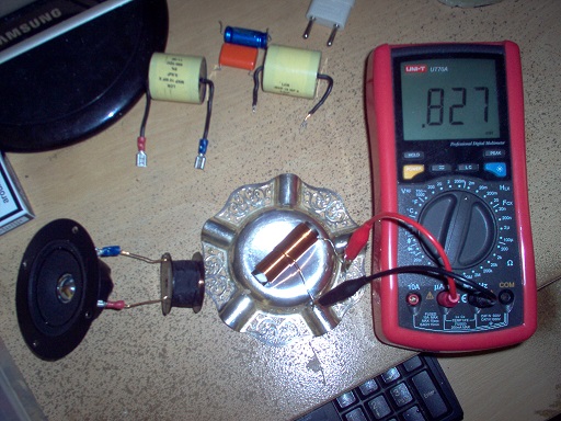
I don't like any PCB really, but let's look at what your one does to your facedown coil on the right.
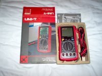
Get's out ashtray and multimeter and 0.3mH plastic bobbin aircoil from Wilmslow...
0.295mH in free air
0.290mH sideways on to ground plane
0.260mH facing silver groundplane
0.275mH facing brass groundplane
It's a question of how much of the magnetic flux is cut by the groundplane and inducing eddy currents.

I'm just making the best of a bad job here.
FWIW, this is related to why Kapton voicecoil formers get a Qms around 5, and cooler running cut aluminium voicecoil formers get typical Qms of 2 in speakers. You'd think the cut stops the eddy currents, but they are sneaky and have more subtle paths between the end and middle of the voicoil, hence the unwanted damping.
Last edited:
I don't like any PCB really, but let's look at what your one does to your facedown coil on the right.
Get's out ashtray and multimeter and 0.3mH plastic bobbin aircoil from Wilmslow...
0.295mH in free air
0.290mH sideways on to ground plane
0.260mH facing silver groundplane
0.275mH facing brass groundplane
It's a question of how much of the magnetic flux is cut by the groundplane and inducing eddy currents.
I'm just making the best of a bad job here.
FWIW, this is related to why Kapton voicecoil formers get a Qms around 5, and cooler running cut aluminium voicecoil formers get typical Qms of 2 in speakers. You'd think the cut stops the eddy currents, but they are sneaky and have more subtle paths between the end and middle of the voicoil, hence the unwanted damping.
Hi Steve,
I just tried this in something a little more realistic. Next time I buy a crossover PCB I'll retest. Instead of a metal ashtray I used a folded sheet of aluminum foil. I measure:
Free air: 1.052 mH / 0.71 DSR
On Foil: 1.048 mH
Difference: 4 uH or about 0.38 %, much better than the 18% loss with an ashtray.
Rotated on foil: 1.0521
While I can see that there is a difference, I think the material and thickness matters. If the PCB is close to half of a percentage point I'm disinclined to care and would be more concerned with the convenience of it's use.
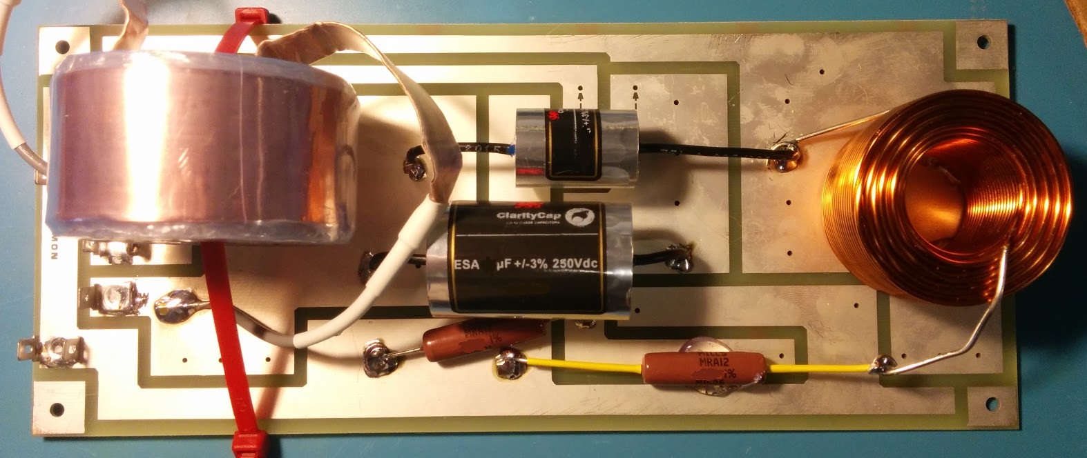
However, I did additional testing with one of the leads connected to the foil. This is rather realistic as I often will use the copper land area under a coil as a connection point. You can see this in the picture I posted on the air wound coil. The top cap seats in a hole in the same copper land that the coil rests on. DATS refused to measure it as a coil anymore. Based on additional testing, what seems to be happening is that there is some capacitance coupling between the coil and the foil throwing everything off. I lack the tools to test this as quickly as with DATS so I won't dig in further.
For me the bigger lesson seems to be that connecting to the copper fill is worse than the inductance loss.
The big lesson for me is not to smoke!
Erik
Last edited:
BTW, sorry, RickH, we seem to have hijacked your thread. But rest assured, your speaker will be better for it. I hope.
That's a very interesting result on inductance change, Erik, and a result I was able to reproduce myself. Which is the beauty of good science!
More layers of similarly sized Aluminium foil produced more effect. Now this surprised my preconceptions, because I considered a mere foil to be sufficiently conducting to behave like a thick layer of metal. Perhaps my radio background, where skin-effect in conductors dominates.
I don't think what I said about aluminium speaker voicecoil formers is affected, because they are quite thick.
But I might upgrade my opinion of boutique capacitors, which have considerably thicker metal foils, rather than the merest skin of almost transparent metal electro-deposited to polymer sheets in cheap film types.
I would warn about being over-complacent here. An inductance meter uses a 1kHz test tone. By the time you get near 20kHz, effects might be much greater. But a pleasure to talk to a real scientist. Measurement is EVERYTHING!
Last edited:
BTW, sorry, RickH, we seem to have hijacked your thread. But rest assured, your speaker will be better for it. I hope.
No problem - I'm still trying to figure out who Eddy Current is and why Erik let him on his crossover.
What about Zaph's SR71 or Mark K's ER18DXT
Okay, let's say I've decided to assemble my own crossover and want to choose between the Seas Idunn kit, Zaph's SR71 and Mark K's ER18DXT. For a 2 channel stereo music system in a 10 x 12 foot room, without a subwoofer, what would you choose?
IDUNN
Zaph|Audio - ZA-SR71
The Seas ER18DXT ported two way
Thank you!
Rick
- Status
- This old topic is closed. If you want to reopen this topic, contact a moderator using the "Report Post" button.
- Home
- Loudspeakers
- Multi-Way
- Need help deciding between the Seas Idunn or Bragi kits