Onni,
Joining this thread late here - really interesting and nice study you have made here. It looks like a lot of the cardiod or super cardiod polar response can be modeled to get a handle on number of holes and placement of holes and also damping in box and vent constriction. I haven't had a chance to read all the posts carefully yet. What made you decide to go with the 8FE200's in the end? I have some Eminence Beta 8Cx that I am wondering if they can work given the low Qts. Alternatively, I have some RS225-8's and a bunch of 5.25in polycone woofers with Qts of 0.44 and Vas of 7liters and fs of 55Hz.
I will start with an Akabak model and add some leaky vents in the side and see what that does to the polars in the model.
Thanks for sharing.
A speaker such as this does not necessarily transition to a dipole at low frequencies...
Hi Keyser,
Agreed! Though I believe if onni can determine how the speaker is behaving down low then it would be easier to determine the next course of action (ie add/reduce resistance; increase resistive path length etc) to extend the cardiod response.
xrk - It would be great to see what you come up with! A dedicated xrk cardiod thread is way overdue!
I'm no expert either, this is entirely new to me!Hi onni, nice project! I'm currently experimenting with gradient type enclosures and believe they have merit too. Sadly I don't have any meaningful/comprehensive measurements (and am far from an expert) but nonetheless have a few questions and thoughts about your project.
What is it about a Supercardiod that you like? Is it the rear nulls that you can aim at the front walls when speakers are toed-in and close to the wall?
I'm not sure if a cardiod/supercardiod woofer and CD waveguide would outperform a monopole woofer and CD waveguide when it comes to having a wider sweet spot. Would be great if they do and am keen to see your results.
From memory, for vent area Kimmo Saunisto recommends 2 x SD but as has been pointed out balancing all the relevant 'cardiod' parameters seems critical to passive cardiod success.
The 'hump' that appears in the lower frequency range of your plots looks like a typical dipole curve (ie first dipole peak). I believe it is pretty common for these type of speakers to transition from cardiod to dipole as they go lower in frequency.
Thank you for sharing your project.
Mark
Aiming the rear null at the wall is indeed the plan (at least approximately) as I don't have any possibilities to vary the position of the speaker. The recommended distance to the front wall for most speakers is a lot more than what I can achieve.
Many argue that the sweet spot for a speaker with controlled directivity is bigger due to the fact that the level from both speakers is (more) constant when moving from one seat in the couch to another. Gettin closer to a speaker and at the same time more off axis approximately cancels each other. The (super-) cardioid behavior is however close to constant when comparing the seats in a couch where the angle maybe varies ~20°. I'll probably end up with something that has a constant directivity at low frequencies (<1 kHz) and a narrower constant directivity at high frequencies.
The leaking area seems to vary a lot between Kimmos designs. In the WTC7ex the lower midrange has 90 % of Sd leaking area, upper midrange has 99 % of Sd. The bass of KS-2125 has 160 % of Sd, I've seen 200 % as well. Somewhere between 90 and 200 % seems like a good guess.
Thanks for following the progress, makes it a lot funnier!
I haven't seen any sims of directivity of leaky cabinets, I would love to though! I should take some time to learn ABEC3, I'm not friends with akabak due to it needing a 32 bit virtual machine.Onni,
Joining this thread late here - really interesting and nice study you have made here. It looks like a lot of the cardiod or super cardiod polar response can be modeled to get a handle on number of holes and placement of holes and also damping in box and vent constriction. I haven't had a chance to read all the posts carefully yet. What made you decide to go with the 8FE200's in the end? I have some Eminence Beta 8Cx that I am wondering if they can work given the low Qts. Alternatively, I have some RS225-8's and a bunch of 5.25in polycone woofers with Qts of 0.44 and Vas of 7liters and fs of 55Hz.
I will start with an Akabak model and add some leaky vents in the side and see what that does to the polars in the model.
Thanks for sharing.
I chose the 8FE200 for a few reasons:
- Cheap (<30 € each with postage)
- Compact for 8" (<210 mm)
- Rear mountable (with included packer)
- Reasonable flat frequency response
- High sensitivity (95 dB)
- Reasonably large Xmax (4.67 mm)
- Discreet looks
- High fs (should reduce the current requirement as I'll need to lift the low end and thereby keep the driver cooler)
- Decent power handling (130 W max, 260 W program)
Thanks for the encouragement!
/Anton
Onni,
I think I will start out modeling your current box with dual 8FE200's (8ohm version?). Can you get me your box internal dimensions (or volume) and external dimensions, placement of drivers on baffle, equivalent CSA of your vents on each side, length of vents?
It looks like a 12in wide x 10in deep x 30in tall box (externally)? I will use some assumed rough numbers to build the Akabak model first, then update with your measured actual dimensions later.
Thanks.
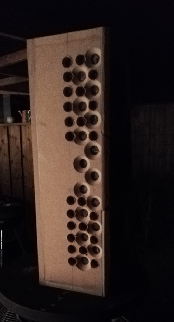
Great! The baffle is 69 cm high (~27") and 25 cm wide (~10") and depth is ( I think..) 20 cm (~8"). It's built out of 19 mm MDF, so internal volume is ~20 l when the volume for drivers and horn is removed. No internal bracing. There are currently a total of 56 holes (28 on each side), all 1" diameter. So a total leaking area of ~284 cm^2. I'll add ~12 more on each side before I make any more measurements.Onni,
I think I will start out modeling your current box with dual 8FE200's (8ohm version?). Can you get me your box internal dimensions (or volume) and external dimensions, placement of drivers on baffle, equivalent CSA of your vents on each side, length of vents?
It looks like a 12in wide x 10in deep x 30in tall box (externally)? I will use some assumed rough numbers to build the Akabak model first, then update with your measured actual dimensions later.
Thanks.
/Anton
Thanks for getting me the dimensions. I was guessing and the size holes I was using (actually approximated with a single tall slot vent) was not getting me a noticeable cardiod response when looking at 360 deg polar. Do you have any polar measurements? I am guessing that it will take a significant leak on the sides to make it cardiod of any appreciable level.
When I get some time, I will put your dimensions into the Akabak model.
When I get some time, I will put your dimensions into the Akabak model.
")
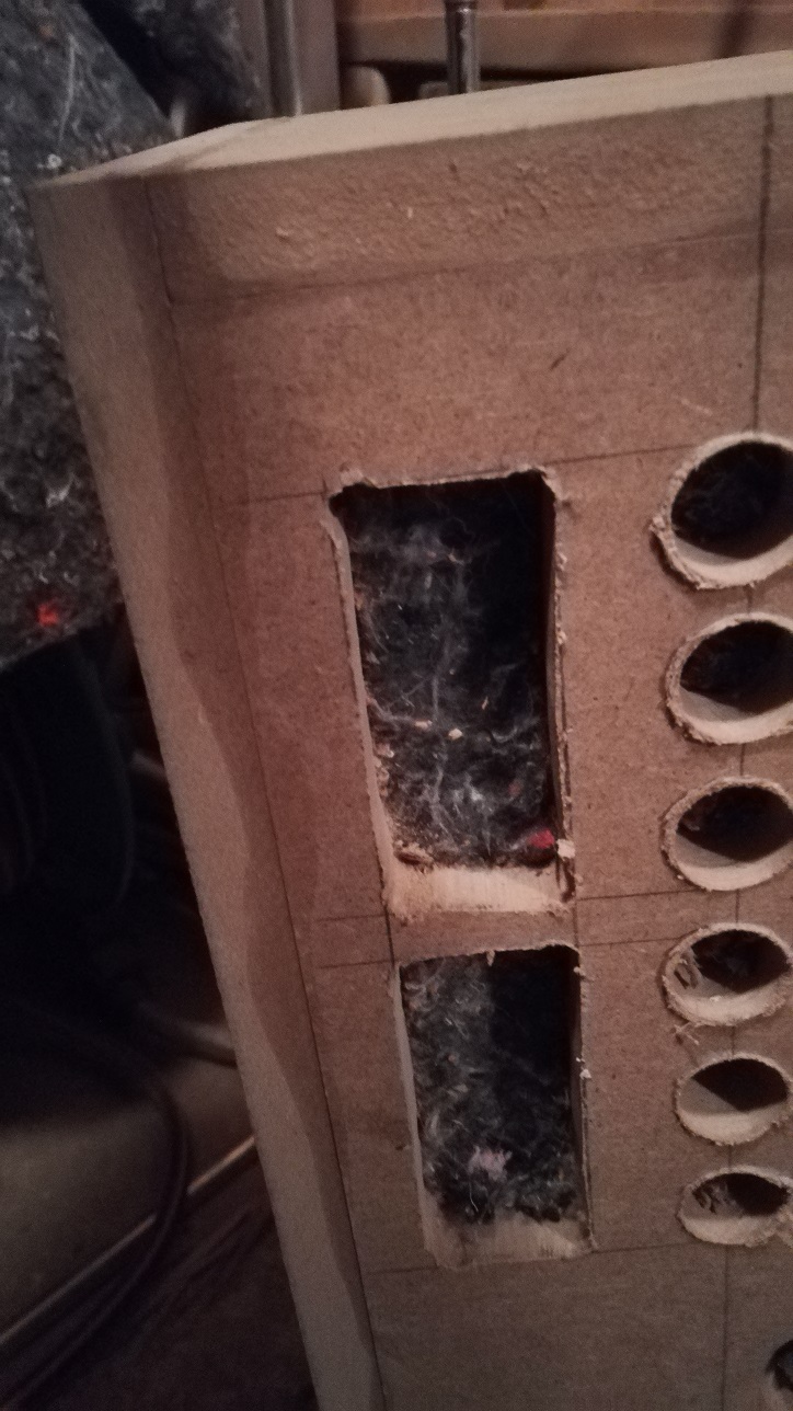
24 more holes drilled (now 106 % Sd):
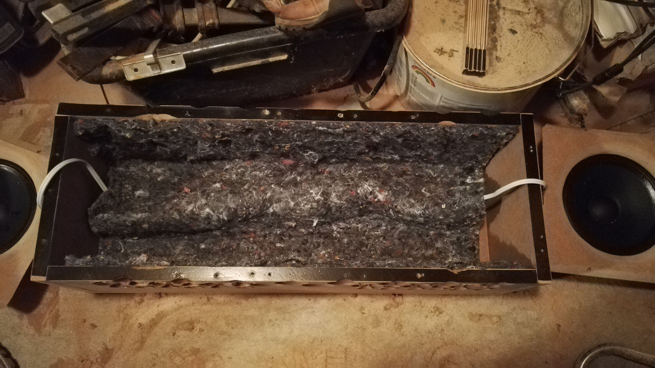
Cotton fabric (flow resistance) is stapled to the MDF:
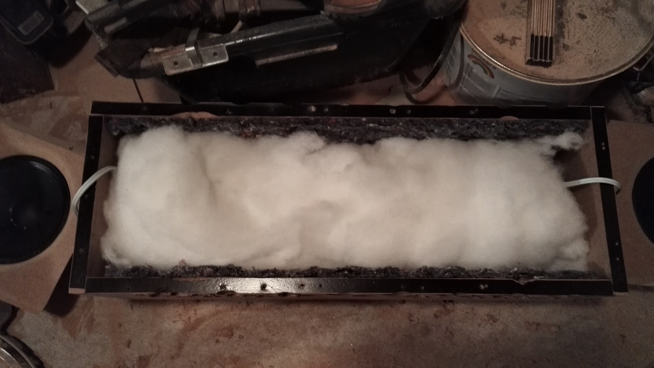
I then added polyester stuffing:
Resulting response:
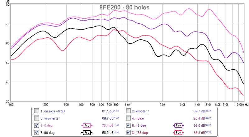
Note that I've expanded the figure to cover 100 Hz-10 kHz (instead of only 100 Hz-2 kHz). Psychoacoustic smoothing, no gating, 1.5 m distance, 1.5 m above ground. I didn't have time to take as many measurements as I've done earlier due to my kid having fever.
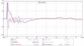
On axis:
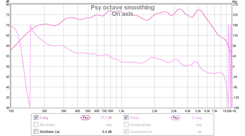
Impulse response:
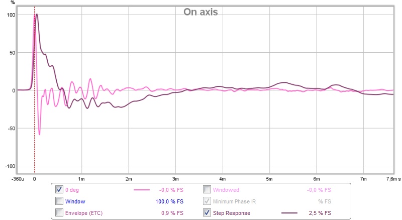
There is some ringing at ~4.5 kHz. Shouldn't be a problem as I'm planning to cross over below 2 kHz.
Are the holes too close to the baffle? Should I make a new test box with the holes moved backwards? I feel the rear-mounting combined with holes very close to the baffle might be less than optimal.
/Anton
Cotton fabric (flow resistance) is stapled to the MDF:
I then added polyester stuffing:
Resulting response:
Note that I've expanded the figure to cover 100 Hz-10 kHz (instead of only 100 Hz-2 kHz). Psychoacoustic smoothing, no gating, 1.5 m distance, 1.5 m above ground. I didn't have time to take as many measurements as I've done earlier due to my kid having fever.
On axis:
Impulse response:
There is some ringing at ~4.5 kHz. Shouldn't be a problem as I'm planning to cross over below 2 kHz.
Are the holes too close to the baffle? Should I make a new test box with the holes moved backwards? I feel the rear-mounting combined with holes very close to the baffle might be less than optimal.
/Anton
Attachments


Last edited:
It's probably easiest to add holes to the current mule boxes and turn the sides to Swiss cheese.
For each enclosure, perhaps aim to get vent area as high as possible (ie above 200% of the combined woofer SD) per enclosure. You could test the affect of increasing the passive delay/path length of the rearward signal by covering holes closer to baffle. You could also examine the affect of increasing the vent area separately and/or together.
For each enclosure, perhaps aim to get vent area as high as possible (ie above 200% of the combined woofer SD) per enclosure. You could test the affect of increasing the passive delay/path length of the rearward signal by covering holes closer to baffle. You could also examine the affect of increasing the vent area separately and/or together.
How is the model coming? I've installed ABEC3 which apparently is almost completely compatible with akabak and runs on 64 bit OS. If you get something running I'd love to get a script to see if I can use ABEC3.Thanks for getting me the dimensions. I was guessing and the size holes I was using (actually approximated with a single tall slot vent) was not getting me a noticeable cardiod response when looking at 360 deg polar. Do you have any polar measurements? I am guessing that it will take a significant leak on the sides to make it cardiod of any appreciable level.
When I get some time, I will put your dimensions into the Akabak model.
/Anton
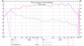
I've not done any polar measurements with the 8FE200 yet, but with the 5" drivers I used initially there is some serious difference between no holes:
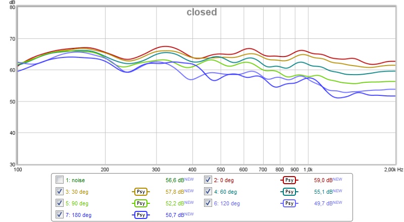
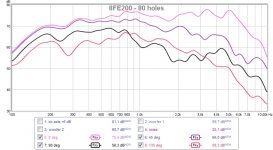
and 56 holes:
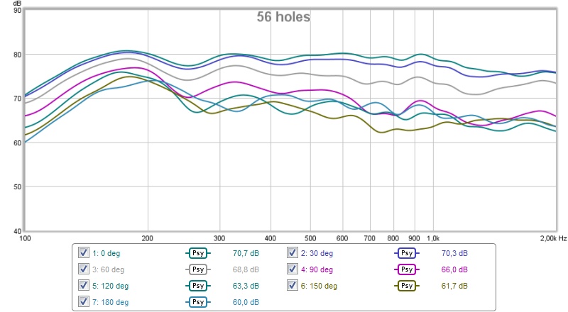
I'll make measurements soon.
/Anton
WOW!.....it even smoothed the on axis response. That's encouraging.
I'm experimenting myself but using two layers of peg board and a third cover board with various shaped......triangle. rectangle, ellipse, circle and the panel is longer than the peg board which allows me to offset the vent overall. Will post some measurements once the test enclosure is done.
No progress I'm afraid. We have about 50 cm of snow and no room that is large enough to do indoors measurements.Anton, what's the status?
The smoother response might be due to the fact that I changed the material in the box from egg-crate type:WOW!.....it even smoothed the on axis response. That's encouraging.
I'm experimenting myself but using two layers of peg board and a third cover board with various shaped......triangle. rectangle, ellipse, circle and the panel is longer than the peg board which allows me to offset the vent overall. Will post some measurements once the test enclosure is done.
An externally hosted image should be here but it was not working when we last tested it.
to glassfiber and polyfill:
An externally hosted image should be here but it was not working when we last tested it.
/Anton
Progress
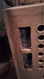
Now I've made more holes:
4 rectangular 90 x 40 mm holes/side added for a total leaking area of (405 + 4*(9*4)*2 = 693 cm^2 = 181 % total Sd) 181 % of total Sd.
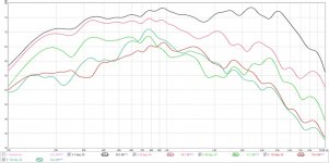
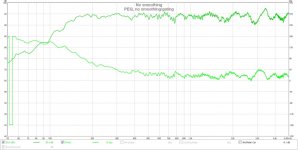
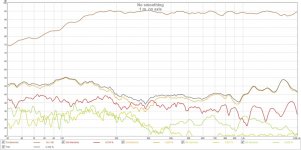
Horisontal polars (0, 45, 90, 135 and 180°):
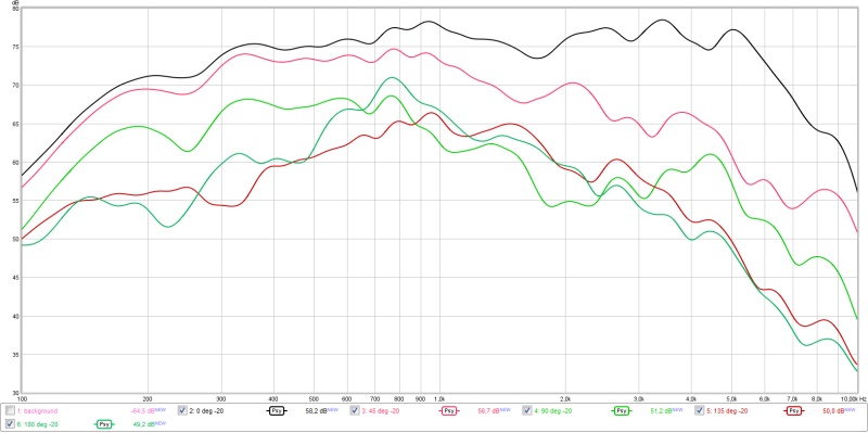
Compared to earlier, 106 % of Sd (180° measurement missing):
Low end separation has improved slightly.
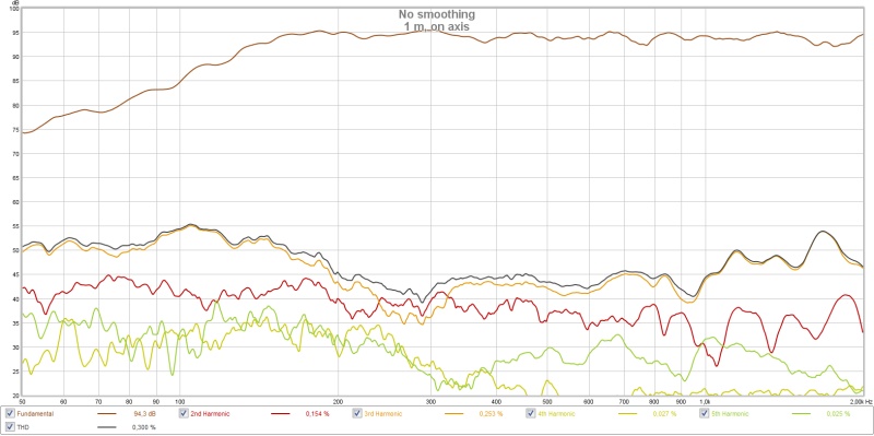
On axis response after EQ (minidsp):

No smoothing or gating.
Distortion at 94 dB:
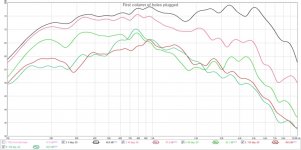
I then tried plugging the first column of holes (closest to baffle) with foam:
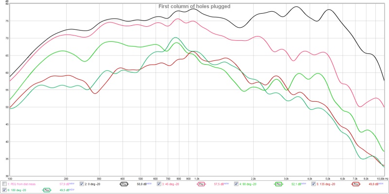
Slight improvement, maybe I need to close the holes off with wood. I'll try this.
/Anton
Now I've made more holes:
4 rectangular 90 x 40 mm holes/side added for a total leaking area of (405 + 4*(9*4)*2 = 693 cm^2 = 181 % total Sd) 181 % of total Sd.
Horisontal polars (0, 45, 90, 135 and 180°):
Compared to earlier, 106 % of Sd (180° measurement missing):
Low end separation has improved slightly.
On axis response after EQ (minidsp):
No smoothing or gating.
Distortion at 94 dB:
I then tried plugging the first column of holes (closest to baffle) with foam:
Slight improvement, maybe I need to close the holes off with wood. I'll try this.
/Anton
Attachments
- Status
- This old topic is closed. If you want to reopen this topic, contact a moderator using the "Report Post" button.
- Home
- Loudspeakers
- Multi-Way
- Leaky supercardioid mids