That works too. Note that the baffle shape changes how the crossover needs to be tuned to handle the difference in a symmetric narrow baffle and now an asymmetric wide baffle. But make sure you seal the internal dividers where they contact the front baffle with gasket material. A small pinhole leak will prevent deepest bass notes from forming. Like a pinhole leak with a finger pad when playing a woodwind instrument.
Thanks.
I've got some great cabinets which I'm recycling and the internal baffle design in my picture will be much easier to install as well as being easier to stuff.
I was thinking along the lines of the IMF TLS 50 so I thought I'd start with their crossover then measure and tweek.
The downside is the amount of gasket I'll need. Oh well.
Try installing basic minimum damping/stuffing and then add some extra wads in mesh bags connected with a string that can be pulled out as needed. You would be surprised by how far you can reach in through the driver cut out. The wall damping should be glued in place (melamine foam pads or eggcrate foam). The polyfill in the main void can be adjusted by hand or using wire coat hanger hooks or mesh bags on a string.
Thanks will update you soon on how its sounds
It started sounding good after couple of issues with crossover however still figuring out the right amount of stuffing
It started sounding good after couple of issues with crossover however still figuring out the right amount of stuffing
What is the ideal stuffing when i am doing stuffing the bass and mids are not correct without stuffing it works good
It’s hard to say, I put quite a bit in and this gives the bass a tight accurate sound, not flappy. The level is not lacking at all - quite substantial. Here is a photo of my polyfill (pillow stuffing):
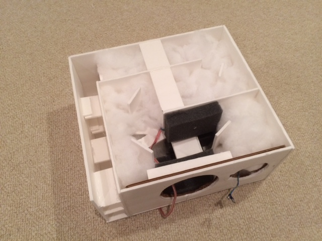
If you look at photos of how PMC does theirs, they use eggcrate foam along one wall basically along whole length. They cover all walls around the driver and use a piece of foam to constrict the passage right below the woofer. I have noticed that many times. Do a google image search for “PMC Transmission Line internal” and you will see what I mean.
Are you using a microphone to measure? Hard to say what’s going on without one.
It’s hard to say, I put quite a bit in and this gives the bass a tight accurate sound, not flappy. The level is not lacking at all - quite substantial. Here is a photo of my polyfill (pillow stuffing):
If you look at photos of how PMC does theirs, they use eggcrate foam along one wall basically along whole length. They cover all walls around the driver and use a piece of foam to constrict the passage right below the woofer. I have noticed that many times. Do a google image search for “PMC Transmission Line internal” and you will see what I mean.
Are you using a microphone to measure? Hard to say what’s going on without one.
Let me try that
If you look at photos of how PMC does theirs, they use eggcrate foam along one wall basically along whole length. They cover all walls around the driver and use a piece of foam to constrict the passage right below the woofer. I have noticed that many times. Do a google image search for “PMC Transmission Line internal” and you will see what I mean.
Hi XRK,
First of all, thanks very much for your superb contributions to the Transmission Line topic. I think, for me at least, these are among the most confusing enclosures. Saying that, the principle is clear to me, the stuffing is most of the time stated as "magic".
Now I'm working from home (COVID-19 virus hassle), I don't have to travel 4 hours a day, leaving me time to dig into it.
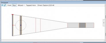
For what it is worth, I am using the LA software to design the TL and found a neat trick on stuffing / damping or whatever it is called. It seems that, as you also noted, the PMC TL's have more damping at the driver location. Using the LA software, I can split the TL in segments and fill each segment with damping material (kg / m3). That way, I can simulate the effect of the damping on the SPL curve, impedance, etc.
I found that there are 3 spots in the TL that effect the behaviour at its max, which is no surprise. At the closed end of the line (impact the roll-off at fb), behind the driver (impact the first and second harmonic bumps) and in the last segment (mostly middle of) which impacts the other harmonics.
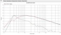
Adding damping along the whole line, mostly results in lower SPL over the effective frequency range of the driver (no surprise I guess). It also flattens the bumps a bit, but not much.
HOW it sounds, I need to build it

See attached picture. I assume this can be explained in the science world, which is way beyond me. However, I think this approach could give me a nice first build version.
Comments / observations much appreciated.
kind regards,
Frans
Attachments
Last edited:
Hi Wae,
Sorry I did not see your post until now. The use of stuffing all along the line is optional and it really does smooth things out at the expense of some loss of SPL. I tried a TL with no stuffing and no damping foam along the labyrinth and it had ripple that cannot be gotten rid of otherwise.
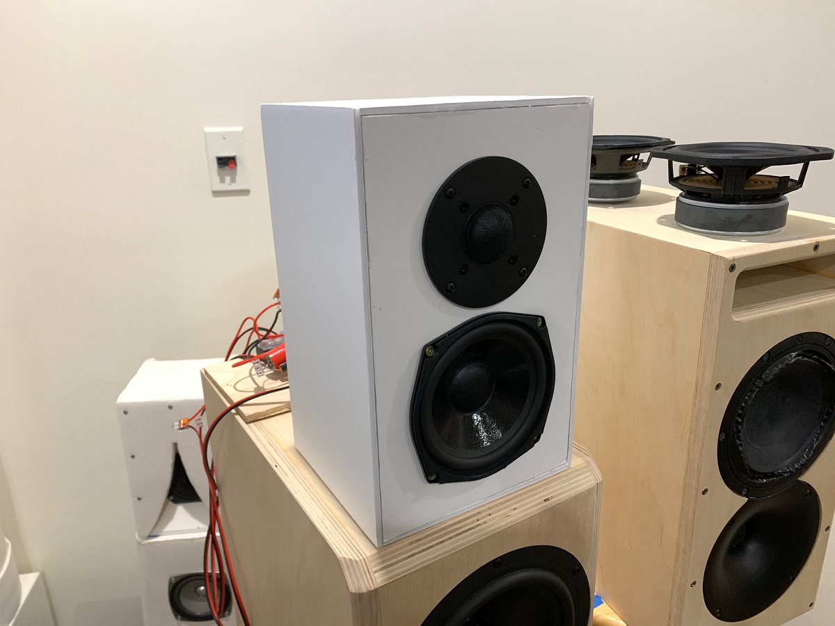
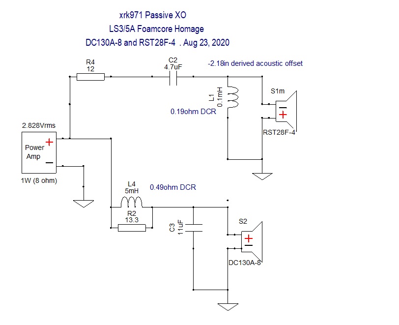
I just made a nice XO design for the DC130A-8 woofer paired with the RST28F tweeter in an LS3/5A size box. The baffle is the same width as this TL. You could use the same XO on this design with a change to the tweeter and get a nice speaker with great midrange, highs (like an LS3/5A in typical frequency response) but now with deep bass to go with it.
RST28F and DC130A Foamcore Homage to LS3/5A
Sorry I did not see your post until now. The use of stuffing all along the line is optional and it really does smooth things out at the expense of some loss of SPL. I tried a TL with no stuffing and no damping foam along the labyrinth and it had ripple that cannot be gotten rid of otherwise.
I just made a nice XO design for the DC130A-8 woofer paired with the RST28F tweeter in an LS3/5A size box. The baffle is the same width as this TL. You could use the same XO on this design with a change to the tweeter and get a nice speaker with great midrange, highs (like an LS3/5A in typical frequency response) but now with deep bass to go with it.
RST28F and DC130A Foamcore Homage to LS3/5A
The LA TL software never really sorted out completely stuffing effects, although it was improved. From my experience placing stuffing in the first 2/3 of a negatively-tapered line, or the first half of an ML-TL will almost always give good results. If a tapered line has a low taper ratio, it will be difficult to smooth out the response without negative affecting the bass reach (and a long non-tapered line is even worse). I've always used at least a 10:1 taper ratio for my designs and as much as 26:1.
Paul
Paul
Good points on the stuffing, Paul. I have noticed that with the low taper lines, they are best just lined with acoustic foam on walls. Stuffing only in closed section up to where the driver is. Sometimes, I put a very small puff of very loose stuffing before the final turn to the vent. This has to be done with an impedance sweep to tune it exactly to the level desired. Literally, 0.5g makes a difference. But it’s very effective in flattening the two tall peaks down to an “horned owl’s head or cat’s head” shape.
If one isn't careful, like trying to tweak the stuffing by ear or just because it's something you can do (but maybe don't really need to do), it's very easy to completely kill the terminus' contribution to the bass response. I've never, ever tweaked stuffing density or location from what I modeled.
Paul
Paul
That’s why it’s important to do it with real time impedance sweep via DATS. You wouldn’t want to adjust the bias current on an amp without a real-time DVM, and this is the same sort of thing. But stuffing variations at the closed end is really insensitive and just helps to smooth the general raggedness of a TL.
From my experience placing stuffing in the first 2/3 of a negatively-tapered line, or the first half of an ML-TL will almost always give good results.
For a tall and narrow br-box, with both the driver and the port mounted closed together in the upper part of the box, should the box still have stuffing in the first 2/3’s? I guess you consider a tall and narrow br box as a mltl?
With the port and driver spaced closely, it's not going to be a good ML-TL design and I don't know offhand how stuffing may need to be located or its density. Yes, a tall and narrow box definitely can be described as an ML-TL. Its performance, that benefits from the box's shape, can be optimized by using software that takes into account the cabinet's internal dimensions as well as the port's dimensions, rather than basing the port's dimensions solely on the cabinet's volume. And just as important, the port's location relative to the woofer's location and the cabinet's internal height can also be optimized, resulting in the smoothest possible overall response shape. An ML-TL usually only needs stuffing in the first half of the line (woofer located near the top of the cabinet and the port near the bottom).
Paul
Paul
Last edited:
Thanks guys for your input (and XRK for firing this up). It has been VERY low on audio and loudspeaker experiments the last months. BUT I still want to get a TL build. That's why I was so inspired by XRK's perfect thread, I even bought 2 Faital drivers he suggested for his TL.
The reason I wanted to figure out if "best practice" TL damping rules can be defined to help improve the popularity of a TL for the audio fans who, just like me, never got the guts to start a TL design. This mystique on damping is a real demotivating factor.
Using the LA software, I started finding a simple pattern on how to start the damping. Reading "start experimenting with damping material" is a bummer for me, I think i will be 90+ years experimenting if I don't have a clue were to start. As stated earlier, I found 3 area where to damp, and they are VERY similar to the PMC approach, so it feels like being forward in finding some rules on damping. SO, somewhere half september 2020, thinks will slow down in my professional life and that's a perfect time to get this going.
If it's OK with you, I may request some input and advice, as you are miles ahead on me.
I have built several TL's now with long tapers like the PMC style, and have been really impressed by the quality of the bass they produce. It's so much better than a regular ported vent, or a passive radiator. I fee that it reduces the compression on the cone and reduces cone movement needed for bass, hence lowers distortion for the same SPL.
Reading this thread because i want to make a small desktop speaker that performs well and is cost effective. This looks like it does.
I have always liked the TL idea, i like to give it a go.
If i use the Faital 5FE120, is the crossover affected? And if so, what would change?
I have always liked the TL idea, i like to give it a go.
If i use the Faital 5FE120, is the crossover affected? And if so, what would change?
You can’t change the driver. It’s a new speaker as far as the TL design is concerned.
There is a passive XO for this woofer and RST28F tweeter here:
RST28F and DC130A Foamcore Homage to LS3/5A
There is a passive XO for this woofer and RST28F tweeter here:
RST28F and DC130A Foamcore Homage to LS3/5A
Is RST28F-4 would fit in directly to DC28F-8? Also can i tweak the tweeter crossover of my build?You can’t change the driver. It’s a new speaker as far as the TL design is concerned.
There is a passive XO for this woofer and RST28F tweeter here:
RST28F and DC130A Foamcore Homage to LS3/5A
- Home
- Loudspeakers
- Multi-Way
- Low-Cost PMC-inspired TL Monitor with DC130A and DC28F