
The Keele CBT uses a curved cabinet.
An externally hosted image should be here but it was not working when we last tested it.
The JBL CBT does not.
I have another thread on a car audio forum where I'm doing a build on my car. And a member raised the idea of doing the delay passively, like JBL does. (his post is here : Car Audio | DiyMobileAudio.com | Car Stereo Forum - View Single Post - 28 Weeks Later )
So I wanted to explore ways to do this but wanted to do it in a separate thread, since the CBT has been discussed more here than there
First, a bit of editorializing:
Another forum member sold his Gedlee Abbeys and purchased CBTs. I was curious about the CBTs also, as Don Keele knows a lot about horns, and for him to switch from horns to arrays, it must be something special.
Based on that, I made the effort to audition the CBTs. I heard them at the Parts Express booth at CES and was underwhelmed. To me, they had that Bose Wave Radio effect, where it's very spacious but the treble is AWOL.
But I started to think about arrays again due to a few conversations I've had. First, Jason Winslow over at Diyma mentioned that Mark Eldridge switched from horns to arrays, and that the arrays sounded better. Second, I talked to Bill Waslo and he spoke very highly about the Keele CBTs that he heard.
So I started to think about giving it another go.
If you look at the horizontal polar response of the Keele CBTs, you can see that there are some issues. This is no different than any horizontal array. I think there's a real argument to be made for flipping the CBT on it's side, similar to what Monte Kay did here:
(more info here : mfk-projects CBT center speaker)
And in the March 2014 issue of Voice Coil magazine, the CBT inventors point out that the 'straight' version measures better than the curved version:
The early CBT versions were implemented with complex curved structures or discrete amplifier channels and DSP to create the time delays and attenuation—while effective, it was also complex and expensive. HARMAN /JBL engineer Doug Button worked with Don Keele on the earlier implementations of CBT and also co- authored AES papers. Button is listed as co-inventor on at least one other CBT patent, set out to explore the possibility of a simpler straight line array, passive filter expression of the CBT formulation. The patent application of this review discloses the outcome of that exploration. Basically, Button developed a method to emulate an electronically time-delayed CBT line array's performance with the use of all-passive components. The principal of operation is based on the notion that group delay with flat amplitude vs. frequency response is no different than an electronically derived time delay. Capacitive and inductive reactive com - ponents create degrees of phase shift expressed as group delay in time. The group delay of a single passive component is not flat with frequency, but combinations of inductors and capacitors can be configured to achieve flat group delay over a wide bandwidth. For many applications, the drawback is the small group delay, per L/C network section. Achieving the appropriate delay at each transducer node in the CBT array is advantageous to develop the ideal delay to provide the prescribed curvature in a straight-line array. The desired delay between each successive transducer is quite small particularly when the transducer diameters and center-to- center spacing is small, which also creates more seamless, wideband pattern control. In the passive CBT system, the desired group delay is derived by tapping points along an L/C/R network with the optimal delay and shading attenuation serially accumulating down the line. Besides the reduced cost and complexity, the passive system is claimed to also improve performance by eliminating disruptions in the smoothness of the dispersion pattern due to quantization issues that are often a side effect of standard digital implementations. While some have claimed that the purest implementation of this type of array, is by way of actual physical curvature instead of electrically derived delay, the "straight array," delay-based systems, tend to maintain the most consistent vertical polar pattern over the full 360° of horizontal angles around the device. For an assessment of CBT vs prior art approaches to directivity control see Keele's most recent AES paper, "A Performance Ranking of Seven Different Types of Loudspeaker Line Arrays". Additionally, to explore the rest of the HARMAN intellectual property on CBT technology, (see US Patent 7684574, US Patent 7826622, and US Patent 8170223). In conclusion, the patent application discloses what appears to be a more practical, simplified, and cost-reduced implementation of the very effective, high performance CBT architecture. Kudos to Don Keele and Doug Button for intro - ducing this interesting technology to the audio industry, and evolving it into an effective and practical system.
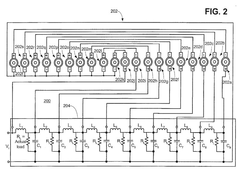
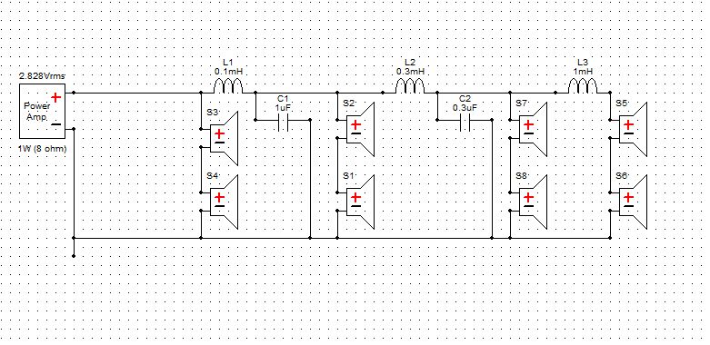
Here is the passive xover for a twenty element CBT array. (via patent Patent EP2247120A2 - Passive group delay beam forming - Google Patents )
Another forum member sold his Gedlee Abbeys and purchased CBTs. I was curious about the CBTs also, as Don Keele knows a lot about horns, and for him to switch from horns to arrays, it must be something special.
Based on that, I made the effort to audition the CBTs. I heard them at the Parts Express booth at CES and was underwhelmed. To me, they had that Bose Wave Radio effect, where it's very spacious but the treble is AWOL.
But I started to think about arrays again due to a few conversations I've had. First, Jason Winslow over at Diyma mentioned that Mark Eldridge switched from horns to arrays, and that the arrays sounded better. Second, I talked to Bill Waslo and he spoke very highly about the Keele CBTs that he heard.
So I started to think about giving it another go.
If you look at the horizontal polar response of the Keele CBTs, you can see that there are some issues. This is no different than any horizontal array. I think there's a real argument to be made for flipping the CBT on it's side, similar to what Monte Kay did here:
(more info here : mfk-projects CBT center speaker)
And in the March 2014 issue of Voice Coil magazine, the CBT inventors point out that the 'straight' version measures better than the curved version:
The early CBT versions were implemented with complex curved structures or discrete amplifier channels and DSP to create the time delays and attenuation—while effective, it was also complex and expensive. HARMAN /JBL engineer Doug Button worked with Don Keele on the earlier implementations of CBT and also co- authored AES papers. Button is listed as co-inventor on at least one other CBT patent, set out to explore the possibility of a simpler straight line array, passive filter expression of the CBT formulation. The patent application of this review discloses the outcome of that exploration. Basically, Button developed a method to emulate an electronically time-delayed CBT line array's performance with the use of all-passive components. The principal of operation is based on the notion that group delay with flat amplitude vs. frequency response is no different than an electronically derived time delay. Capacitive and inductive reactive com - ponents create degrees of phase shift expressed as group delay in time. The group delay of a single passive component is not flat with frequency, but combinations of inductors and capacitors can be configured to achieve flat group delay over a wide bandwidth. For many applications, the drawback is the small group delay, per L/C network section. Achieving the appropriate delay at each transducer node in the CBT array is advantageous to develop the ideal delay to provide the prescribed curvature in a straight-line array. The desired delay between each successive transducer is quite small particularly when the transducer diameters and center-to- center spacing is small, which also creates more seamless, wideband pattern control. In the passive CBT system, the desired group delay is derived by tapping points along an L/C/R network with the optimal delay and shading attenuation serially accumulating down the line. Besides the reduced cost and complexity, the passive system is claimed to also improve performance by eliminating disruptions in the smoothness of the dispersion pattern due to quantization issues that are often a side effect of standard digital implementations. While some have claimed that the purest implementation of this type of array, is by way of actual physical curvature instead of electrically derived delay, the "straight array," delay-based systems, tend to maintain the most consistent vertical polar pattern over the full 360° of horizontal angles around the device. For an assessment of CBT vs prior art approaches to directivity control see Keele's most recent AES paper, "A Performance Ranking of Seven Different Types of Loudspeaker Line Arrays". Additionally, to explore the rest of the HARMAN intellectual property on CBT technology, (see US Patent 7684574, US Patent 7826622, and US Patent 8170223). In conclusion, the patent application discloses what appears to be a more practical, simplified, and cost-reduced implementation of the very effective, high performance CBT architecture. Kudos to Don Keele and Doug Button for intro - ducing this interesting technology to the audio industry, and evolving it into an effective and practical system.
Here is the passive xover for a twenty element CBT array. (via patent Patent EP2247120A2 - Passive group delay beam forming - Google Patents )
I don't think that hornresp can model that xover network.
There are some spreadsheets that can do it, but I'm not certain that they can plot group delay. (Hornresp can plot the delay, but can't deal with the complexity of that network.)
Eight years ago I used Speaker Workshop to model xover networks, so let's give that a go.
The audua website is long dead, but the program is still available via the wayback machine here:
https://web.archive.org/web/20130306051307/http://www.speakerworkshop.com/Files/Spkrwork.zip
I did some research, and found that the crossover in the speaker that JBL sells is quite a bit different than the crossover in the patent.
This is good news actually! To me, the most obvious way of curving the wavefront is to use DSP or a curved baffle. But if you don't go that route, the most obvious solution is to use a low pass filter to delay the drivers on the top and bottom of the array. Basically you run the center drivers with a full range signal, and then you low pass the outer drivers. The low pass filter introduces a delay. Off the top of my head, a second order low pass will introduce one half wavelength of delay.
For instance, if you need to delay the outside drivers by seventeen centimeters, you could use a second order low pass filter at 1000hz to achieve that delay. (1000hz is thirty four centimeters long, and the second order delay introduces one half wavelength of delay.)

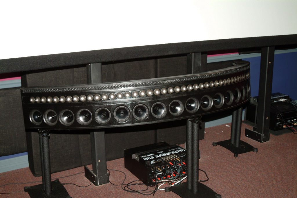
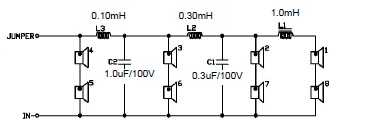
Here's the actual crossover in the loudspeaker. Methinks that's just what they did - note that the four drivers in the center are running full range, while the drivers above and below are progressively delayed via a second order low pass.
Or at least I THINK that's what's going on 🙂
This is good news actually! To me, the most obvious way of curving the wavefront is to use DSP or a curved baffle. But if you don't go that route, the most obvious solution is to use a low pass filter to delay the drivers on the top and bottom of the array. Basically you run the center drivers with a full range signal, and then you low pass the outer drivers. The low pass filter introduces a delay. Off the top of my head, a second order low pass will introduce one half wavelength of delay.
For instance, if you need to delay the outside drivers by seventeen centimeters, you could use a second order low pass filter at 1000hz to achieve that delay. (1000hz is thirty four centimeters long, and the second order delay introduces one half wavelength of delay.)
Here's the actual crossover in the loudspeaker. Methinks that's just what they did - note that the four drivers in the center are running full range, while the drivers above and below are progressively delayed via a second order low pass.
Or at least I THINK that's what's going on 🙂

A couple of other random observations about the xover:
1) there are a bunch of jumpers in the xover. I think those are there so that the user can choose the beamwidth. For instance, you could change the wavefront shape by changing the xover point on the drivers. Basically you can *narrow* the beamwidth by moving the xover point UP, and vice versa. That's what the jumpers are there for - they modify the capacitance value in the second order low pass network.
2) The manual mentions that there's a transformer in the circuit. Again, I think this has to do with the switches that set the beamwidth. By using a transformer you can have multiple taps, which would allow for multiple inductance levels for the inductors in the circuit.
Both of these items are ways for JBL to offer the end user a variety of beamwidths, without resorting to the expense of having two crossovers. Basically a clever way of giving the end user the flexibility of a DSP xover without the expense of ten amp channels and DSP channels.
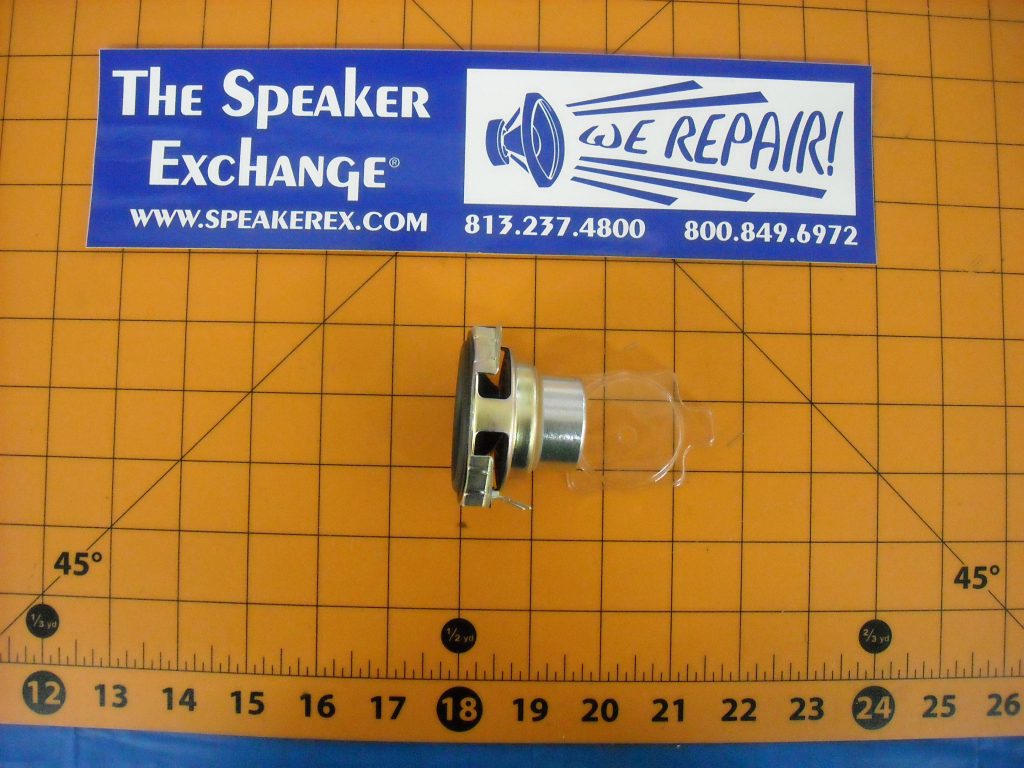
Looks like you could build one of these fairly easily. The drivers and the crossovers are both available. The former is JBL part number 442845.
Linking a related thread
http://www.diyaudio.com/forums/multi-way/254402-straight-line-cbt-array.html
http://www.diyaudio.com/forums/multi-way/254402-straight-line-cbt-array.html
Linking a related thread
http://www.diyaudio.com/forums/multi-way/254402-straight-line-cbt-array.html
Excellent! Lots of good info in there. You were a year ahead of me 🙂
Good news!
It appears that the circuit is remarkably insensitive to driver parameters.
IE, you can pretty much just copy the JBL crossover. Heck, you could probably just BUY the crossover and use it with your drivers.
(Note that the beamwidth of the array will depend on the center-to-center spacing. Therefore, if you used a driver larger than JBLs, the beamwidth would be smaller, and if you used a driver smaller than JBLs, the beamwidth would be wider.)
Kudos to Bill Waslo - his program does indeed model this very well.
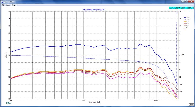
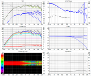
Here is the overall frequency response of the array, and of the individual elements. Note that there's very little response shaping here. The real reason for the xover values is...

Delay. This is a delay network. We can see that there's zero delay on the two drivers in the center (in orange), but the drivers flanking the center are delayed more and more and more.
I still have a questionsthough:
The delays appear to be too small. For instance, the outside woofer in the array should be delayed at least fifteen or twenty centimeters. That would correspond to a delay of 441us - 588us.
It's possible that that increasing the impedance would change this.
I copied the values verbatim from JBL's spec sheet, then plugged them into Bill's xover program.
It appears that the circuit is remarkably insensitive to driver parameters.
IE, you can pretty much just copy the JBL crossover. Heck, you could probably just BUY the crossover and use it with your drivers.
(Note that the beamwidth of the array will depend on the center-to-center spacing. Therefore, if you used a driver larger than JBLs, the beamwidth would be smaller, and if you used a driver smaller than JBLs, the beamwidth would be wider.)
Kudos to Bill Waslo - his program does indeed model this very well.
Here is the overall frequency response of the array, and of the individual elements. Note that there's very little response shaping here. The real reason for the xover values is...
Delay. This is a delay network. We can see that there's zero delay on the two drivers in the center (in orange), but the drivers flanking the center are delayed more and more and more.
I still have a questionsthough:
The delays appear to be too small. For instance, the outside woofer in the array should be delayed at least fifteen or twenty centimeters. That would correspond to a delay of 441us - 588us.
It's possible that that increasing the impedance would change this.
I copied the values verbatim from JBL's spec sheet, then plugged them into Bill's xover program.
Linking a related thread
http://www.diyaudio.com/forums/multi-way/254402-straight-line-cbt-array.html
In your thread you stated the following:
" LC ladder networks create delays at each stage equal to the root of LC product at that stage."
I noticed that when I went from two drivers in series to one driver, the delay didn't change.
This means one of two things:
1) the delay network doesn't care what the impedance of the drivers is
or
2) my sim is off, and I need to simulate the drivers in series as a single element. (IE, instead of simulating two drivers in series, I create a single driver in the crossover model with parameters identical to two drivers in series.)
The delays are
a) Not sufficient
b) Not constant across frequency
This will result in quite a lot of deviation from CBT theory. This means that the speaker will have a different spectral balance when near and far.
However, for home listening situations where the distance from speaker to listener does not change much and given that the ear is forgiving in the vertical plane means, it may still work quite nicely.
OK, I think I figured it out. Please read my earlier posts from today with a grain of salt; it took me a little while to figure out what the heck they were doing.
IMHO, here is what's going on:
1) A low pass crossover filter will add delay. The amount of delay depends on the order. For instance, a 2nd order low pass will add one half wavelength of delay at the crossover point. IE, if you used a 2nd order low pass xover of 1000hz, you'd get 17cm of delay at 1000hz.
2) As you go higher in order, the delay gets longer and longer. 4th order has double the delay of 2nd order.
The thing about the JBL design that had me stumbed was that the values were very small, and the delays were small too.
But I figured it out!
The reason that the values are small is that the xover point is very high. Something like 16khz.
The reason that the delays are small is because they're not curving the array very much. Just ten degrees.
What they're doing is that they've put a 16khz low pass on each section of woofers. The key is that the ORDER goes higher and higher as you get further and further from the center:
Now, the obvious question, why didn't they use more delay?
The answer is simple - if they used more delay they'd have to move the xover point down from 16000hz. IE, the more you curve the array, the lower the xover point has to be, at least with this topology.
IMHO, here is what's going on:
1) A low pass crossover filter will add delay. The amount of delay depends on the order. For instance, a 2nd order low pass will add one half wavelength of delay at the crossover point. IE, if you used a 2nd order low pass xover of 1000hz, you'd get 17cm of delay at 1000hz.
2) As you go higher in order, the delay gets longer and longer. 4th order has double the delay of 2nd order.
The thing about the JBL design that had me stumbed was that the values were very small, and the delays were small too.
But I figured it out!
The reason that the values are small is that the xover point is very high. Something like 16khz.
The reason that the delays are small is because they're not curving the array very much. Just ten degrees.
What they're doing is that they've put a 16khz low pass on each section of woofers. The key is that the ORDER goes higher and higher as you get further and further from the center:
- the center woofers have no delay and no xover whatsoever
- the woofers above and below the center have a 2nd order low pass at 16khz (one half wavelength of delay, or 0.42")
- the woofers above and below that have a 4th order low pass at 16khz (one full wavelength of delay, or 0.84")
- the top and bottom woofers have a 5th order low pass at 16khz (1.25 wavelengths, or 1.05")
Now, the obvious question, why didn't they use more delay?
The answer is simple - if they used more delay they'd have to move the xover point down from 16000hz. IE, the more you curve the array, the lower the xover point has to be, at least with this topology.
The delays are
a) Not sufficient
b) Not constant across frequency
This will result in quite a lot of deviation from CBT theory. This means that the speaker will have a different spectral balance when near and far.
However, for home listening situations where the distance from speaker to listener does not change much and given that the ear is forgiving in the vertical plane means, it may still work quite nicely.
Looks like it's ok. The very small delay is because there's very little curvature.
The variance in delay probably isn't a huge deal, because there's so little delay to begin with. (IE, who cares if your delay is .5" instead of 0.75" at 500hz?)
JBL array provides narrow and wide beam width settings. Which is a better beam width in home listening application? I had asked this question in this thread http://www.diyaudio.com/forums/multi-way/256056-how-narrow-should-vertical-listening-window.html
JBL uses 120x100 in their flagship.
B&O uses something like 180x20 in theirs.
So it really depends on who you ask.
B&O uses something like 180x20 in theirs.
So it really depends on who you ask.
JBL array provides narrow and wide beam width settings. Which is a better beam width in home listening application? I had asked this question in this thread http://www.diyaudio.com/forums/multi-way/256056-how-narrow-should-vertical-listening-window.html
My reasoning is that you would want the vertical beamwidth to be as wide as possible, but you want response to be down 15 or 20 dB at the angles corresponding to floor and ceiling bounces. This allows for the tallest listening window possible without the vertical reflections that change the tonal character of the speaker.
Interestingly, if you reduce the magnitude of the floor and ceiling bounces without reducing the level of the lateral reflections off the walls, the sound will likely become more enveloping rather than less. This is because you will have reduced interaural cross-correlation.
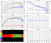
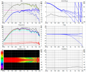
I found this old thread while playing with the idea of short curved arrays. I just put together a quick and dirty simulation of 8 element 3FE22 array (only with 0 and 45 deg measurements) in VituixCAD. Do these results make any sense? First is a flat baffle without the circuit, second is the flat baffle with the circuit and the third one is curved baffle with 1 m radius and the circuit.
Attachments
- Home
- Loudspeakers
- Multi-Way
- Passive Loudspeaker Delay