Hello all,
I'm starting a project to refresh the XO of my 802s3. In fact, to build new ones from scratch.
The original crossovers are built with basic components (electrolytic capacitors, iron core coils) which I'm aiming to upgrade.
I'm aware that the original system was calculated with component imperfections accounted for and I want to compensate for this. I also intend to match the DCR of all coils and ESR of all caps.
Here is the schematic of original B&W crossovers.

source: B&W crossover rebuild
C1 and C2 are MKP
C3, C4 and C5 are Electrolytic
L1 is Air core
L2, L3 is P-Core
L4, L5 is Ferrite core
I'm especially careful about C3 and C4 which I want to replace with MKP.
Assuming a D.F. of 0.03% for these capacitors, I planned to add approx 0.15Ohm in series with C3 and 0.33Ohm in series with C4 to compensate for the difference, however the DF is frequency dependent and my approximations are therefore not perfect. The frequency cutoff points may be affected. Is there any other way to better simulate the behavior of Electrolytics in this circuit?
I will use electrolytic for C5. Or should I not?
Can I use an air core coil with higher ESR for L2 and compensate for the difference with R1 values? The original is a P-Core with approx 0.2 DCR.
Same question for L3. Can I use an air core coil with higher ESR to compensate for lower ESR of the C4?
The component types I plan to use are following:
C1, C2 - Mundorf Supreme
C3 - Mundorf EVO 22uF + Mundorf Supreme 3.9uF (or Jantzen Superior 3.9uF)
C4 - Mundorf Evo 10uF
R1, R2 - Mills or Jantzen Superes (any recommendations?)
L1 - Air Core 0.4mm wire Jantzen
L2, L3 - Mundorf copper foil 14mm I-core (Feron core) (or air core coils if I can compensate for their increased DCR)
L4, L5 - Mundorf 1.4mm (Feron core)
I'd appreciate any tips.
I'm starting a project to refresh the XO of my 802s3. In fact, to build new ones from scratch.
The original crossovers are built with basic components (electrolytic capacitors, iron core coils) which I'm aiming to upgrade.
I'm aware that the original system was calculated with component imperfections accounted for and I want to compensate for this. I also intend to match the DCR of all coils and ESR of all caps.
Here is the schematic of original B&W crossovers.
source: B&W crossover rebuild
C1 and C2 are MKP
C3, C4 and C5 are Electrolytic
L1 is Air core
L2, L3 is P-Core
L4, L5 is Ferrite core
I'm especially careful about C3 and C4 which I want to replace with MKP.
Assuming a D.F. of 0.03% for these capacitors, I planned to add approx 0.15Ohm in series with C3 and 0.33Ohm in series with C4 to compensate for the difference, however the DF is frequency dependent and my approximations are therefore not perfect. The frequency cutoff points may be affected. Is there any other way to better simulate the behavior of Electrolytics in this circuit?
I will use electrolytic for C5. Or should I not?
Can I use an air core coil with higher ESR for L2 and compensate for the difference with R1 values? The original is a P-Core with approx 0.2 DCR.
Same question for L3. Can I use an air core coil with higher ESR to compensate for lower ESR of the C4?
The component types I plan to use are following:
C1, C2 - Mundorf Supreme
C3 - Mundorf EVO 22uF + Mundorf Supreme 3.9uF (or Jantzen Superior 3.9uF)
C4 - Mundorf Evo 10uF
R1, R2 - Mills or Jantzen Superes (any recommendations?)
L1 - Air Core 0.4mm wire Jantzen
L2, L3 - Mundorf copper foil 14mm I-core (Feron core) (or air core coils if I can compensate for their increased DCR)
L4, L5 - Mundorf 1.4mm (Feron core)
I'd appreciate any tips.
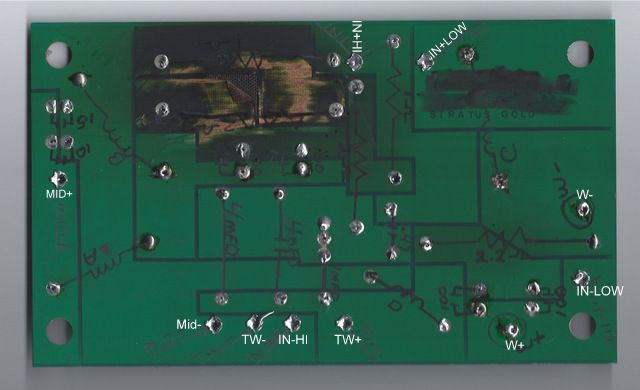
There are some photos of the original crossover, as well as his own ones `on the website of Graham O'Neill
B&W crossover photos
Lots of good information there, but I don't think he followed through with value matching.
I'm in Switzerland, but will be ordering my parts from Hificollective (UK) as they have all I need and want.
I can organize an LCR meter, no problem.
B&W crossover photos
Lots of good information there, but I don't think he followed through with value matching.
I'm in Switzerland, but will be ordering my parts from Hificollective (UK) as they have all I need and want.
I can organize an LCR meter, no problem.
Also, what are your end goals? Are you happy with imaging etc?
I find B&W crossovers have a very particular voicing, which I can only describe as fluffy... they're not as analytical as they can be, but are a very easy listen.
There's a very important question of what do you want to achieve, and would you consider a re-design?
I find B&W crossovers have a very particular voicing, which I can only describe as fluffy... they're not as analytical as they can be, but are a very easy listen.
There's a very important question of what do you want to achieve, and would you consider a re-design?
My goal is to clean up the sound a little bit. I'm happy with the imaging and overall balance, but I feel they're a bit dull, grey overall and hazy in the very top end.
I have another set of boxes based on D260 and a Davis woofers, and while they can't quite keep up with midrange detail, they are smoother and more involving.
I wouldn't mind a bit more speed at the bass, at expense of weight. Can I tweak R2/C5 values somehow to achieve this?
As for a re-design - I'd rather not, I don't have the resources or parts to fine tune the end effect and I want to keep it close to the original.
Givem all that you've said, I'd be looking at replacing the capacitors only and keeping the inductors - changing the inductors is likely to be costly and compromise the sound. Small variations in the DCR of the inductors will effect the transfer functions of the network and could mess up BSC etc.
Going that route, personally I'd be looking at mundorf supremes in the tweeter circuit, standard m-cap for the woofer bypass, and evo for the mid cap bypass.
The 26uF series cap in the midrange I'd personally replace with a 22uF & 4.7uF Evo oil, though if you realy wanted you could change the 4.7 to a supereme - I wouldn't see any advantage to doing that though.
One advantage of ordering through mundorf/hi-fi collective is they match all the components for you to very tight tolerances.
If you wanted to tweak, personally I'd look at reducing the series resistance on the mid either to 0 or with bypass resistors (you could check that immediately with a little wire around the resistot, that way you can remove it without any physical alterations), I'd almost definately increas the 4.7 cap to 5.6, and probably swap the values of L2 and L3... those observations are made from previous experience with B&W xo's.
Thanks a lot for the tips. I planned to build new XO's anyway, as I intend to keep the originals for comparisons sake. In any case I want to match DCR down to <0.03 Ohm or better.
Could you please explain your reasoning for changing C1 from 4.7uF to 5.6uF?
Also, why would C3 = 22uF+4.7uF be a better match than 22uF+3.9uF?
Wouldn't swapping L2 and L3 values affect the frequency cutoff points?
Also, would you suggest keeping C4 electrolytic or is my suggestion of MKP + series resistor reasonable?
A couple of questions to more experienced DIYers:
1. What effect could I expect by using MKP C4 without a series resistance to compensate for the ESR of the electrolytic which is there by design? I used a crossover simulator software with idealized 8ohm load and I can only see a very minor shift (~0.2dB) in SPL and an equally small group delay shift.
Original (10uF + estimated 0.7R ESR):
Modified (10uF + estimated 0.1R ESR):
Could the effect be much more pronounced if simulated with real instead of idealized load?
2. I tried simulating the effect of R2/C2 notch filter but failed. How can I estimate the frequency affected by this filter? Can I tune the bass response by modifying R2 (lower R2 = stronger attenuation at filter frequency?)
1. What effect could I expect by using MKP C4 without a series resistance to compensate for the ESR of the electrolytic which is there by design? I used a crossover simulator software with idealized 8ohm load and I can only see a very minor shift (~0.2dB) in SPL and an equally small group delay shift.
Original (10uF + estimated 0.7R ESR):
An externally hosted image should be here but it was not working when we last tested it.
An externally hosted image should be here but it was not working when we last tested it.
Modified (10uF + estimated 0.1R ESR):
An externally hosted image should be here but it was not working when we last tested it.
An externally hosted image should be here but it was not working when we last tested it.
Could the effect be much more pronounced if simulated with real instead of idealized load?
2. I tried simulating the effect of R2/C2 notch filter but failed. How can I estimate the frequency affected by this filter? Can I tune the bass response by modifying R2 (lower R2 = stronger attenuation at filter frequency?)
glina,
sorry, feel like I'm really letting you down as haven't had time to come back to this (middle of dissertation) will give it the time it deserves shortly, let's not mess about - if you're set on re-building from scratch you may as well improve at the same time.
Do you have any ways to measure transfer function of current xo and speaker response??
I have a plot of the difference here. A tweeter (green) has the crossover applied (blue) to be close to the target slope (black). This has been done using a full impedance plot.Could the effect be much more pronounced if simulated with real instead of idealized load?
Where the impedance magnitude (level) of the plot is correct but phase information is missing (zeroed in this case) the response will come out on the simulator as shown in pink. When pure resistance has been used, you'll get the yellow plot for 8Ω, cyan for 12.
It will not be possible to have confidence in a simulation to the level you seek unless you have impedance plus phase information, and of course acoustic (frequency response) plots for each driver. For the combined responses you'll also need acoustic phase (e.g. four plots per driver).
To re-engineer the crossover for improved performance I would take directivity plots seeking the power response of the drivers to augment the single plots.. and for finding the right angle to listen at.
Attachments
If you use a film for C3 you can make up for the ESR difference by allocating that resistance to a higher DCR inductor.
If you really want to put money into them air core inductors are fine, I wouldn't worry about a tenth of an ohm or two difference but on the other hand can you get 16 or even 14 ga inductors there?
C5 has a .56R in series, so there is at least some resistance to limit the Q, also if you go air core for L4 any increase there in DCR will lower the Q of L4-C5 low pass.
I would not change values since these are fine speakers that were designed with computer optimization. You could certainly lower R1 if you want more midrange output, easy to try.
The best thing would be to measure each sections frequency response and then adjust resistors such as R2 to provide the same response shape. You can measure with ARTA, it is free and you just have to make probes.
Are you sure that the DF of the originals was 3%?
Last edited:
Thank you all.
Since my last post, I've built a model of these crossovers with XSim. The model is based on simulated 8ohm loads and all drivers in line. All phase relations are obviously off. My goal was to match the response of both crossovers and my educated guess is that with this achieved, the end result will also be a close match. I'm currently within 0.3dB of original with parts currently on my shopping list.
I don't feel confident enough to redesign or build a crossover from scratch for a 3 way system of drivers for which there are no published specifications. I'd rather learn on something much more basic.
Anyway, I'm attaching the XSim models for my simulations.
The original includes accurate DCR and ESR values. The modified is based on my shopping list consisting of the following components:
HF:
Mundorf Supreme caps and Mundorf baked varnished air core coil 0.5mm wire
MF:
Mundorf Evo Oil caps and Mundorf baked varnished air core coils 1.4mm wire
LF:
Mundorf laminated steel core and copper foil coils and the 150uF cap will be made of 10x15uF Evox MMK which I happen to have.
resistors are all Jantzen Superes 10W non inductive wire wound (2x 3.6W to create 1.8R and 1.3R+1.5R to create 0.7R).
The only deliberate change I made is to use slightly lower DCR coils (0.2 ohm instead of 0.28 ohm) in order to overdamp the woofers a bit.
Attached are the XSim simulation files. As a bonus, also attached is the crossover model of B&W 801s3 and measured SPL graph. Interestingly, there is an apparent hump at 600Hz and a dip around 3KHz which are also visible on my simplified crossover simulation.
View attachment B&W 802s3.zip
Last edited:
When it comes to performing operations with something like impedance and its phase component, they can't be looked at separately, they act as one.All phase relations are obviously off.
Your results might be ok for a new speaker if you were looking for a starting point. You would then go through and fix the issues. With a known good crossover design it will take more than this to find an improvement.
You could do it all by trial and error taking response plots at each change... Still, measuring impedance doesn't take too much to set up. Soundcard, amp, leads, a few resistors, and setting up and learning to use an analyser.
When it comes to performing operations with something like impedance and its phase component, they can't be looked at separately, they act as one.
What I ment to say was that phase relations between simulated drivers are not true to life.
However, the simulated phase and impedance response of both original and modified crossovers is a nearly perfect match.
Ok, I see.
The woofer capacitor has its parasitics partially swamped by the small series resistor, and sitting behind some inductance. There may not be a noticeable difference changing this cap while retaining the existing resistances.
I'd suspect similarly for the mid crossover for the same reasons, but the series resistances are easily adjusted as PB2 has mentioned.
If R2 is only included for improving the performance of the cap, then maybe if you change them then lowering this resistance might make an improvement by changing the response, but this is just a guess.
Indeed you are right, my simulation shows that R2 + C5 combination has a very strong influence on woofer response. Surprising that B&W chose 10% tolerance parts to go in there.
I will certainly be tweaking these values. My choice of Evox MMK is probably overkill for this place, but most of all I want to be sure that what I set up today will keep its parameters for years.
I will certainly be tweaking these values. My choice of Evox MMK is probably overkill for this place, but most of all I want to be sure that what I set up today will keep its parameters for years.
I know this post is old, but if someone wants to chime in great. I have a pair of 802 S3's and have replaced all caps with films (not touching the inductors). I think they sound great, but after reading posts here (mainly from Glinda) they may be a little forward.Indeed you are right, my simulation shows that R2 + C5 combination has a very strong influence on woofer response. Surprising that B&W chose 10% tolerance parts to go in there.
I will certainly be tweaking these values. My choice of Evox MMK is probably overkill for this place, but most of all I want to be sure that what I set up today will keep its parameters for years.
I have been exercising Glinda's Xsim model and come to some conclusions, that may or may not be correct,
1) I do not see a need to compensate for ESR on any cap other than possibly the 26uF one as this does not change anything much at all. R2 and C5 seem to be best left alone.
2) The model seems to use a 5% DF in it. Has this been verified with the Bennic caps? I no longer have the originals and cannot check them.
3) I am tempted to put 0.5 to 0.6 ohms in series with the 26uF cap to soften the hump around 615 MHz. This would correspond to a DF of 10% if that is what the original electrolytic had.
Any response is welcome.
- Status
- This old topic is closed. If you want to reopen this topic, contact a moderator using the "Report Post" button.
- Home
- Loudspeakers
- Multi-Way
- B&W Matrix 802 S3 crossover refresh