Hello folks,
I am looking to build an open baffle woofer line array to go with my electrostat panels. The upper crossover frequency is 4xx Hz, and the tower should go as low as possible, although I intend to cross it over to a sub anyway.
I want the tower to be as narrow as possible, so that means a U frame.
It seems I have a tradeoff here where if I want the tower to go lower, I need a deeper frame, yet that would make the open pipe resonance of the frame lower as well.
Is there some trick I can use to suppress the upper resonance peak (without actually adding in stuffing)? Here are just some ideas I randomly made up:
1) make the two backwards folded wings of different lengths
2) cut some holes in the wings at a specific location to kill the resonance frequency
3) not have the wings be a constant length, but have a wavy edge, e.g. alternates between 5-9" deep
4) ???
Last edited:
No free lunch as they say.
maybe stupid, but can't you just eq the peak out? Does anyone know how badly a u frame resonant peak rings?
maybe stupid, but can't you just eq the peak out? Does anyone know how badly a u frame resonant peak rings?
Overkill Audio has used a 'wavy edge' successfully on several designs. Derek even has a name for it: VPL or Variable Path Length (not Visible Panty Line!). Asymmetric wings will have an effect too. Best thing to do is build some mockups and proceed empirically- measure them to get a feel for the effect of geometry and how much usable bandwidth it will get you. EQ can always be added once you have your preferred compromise on the physical design established.
Last edited:
Variable Path Length ...A free lunch?!
Hi Beanbag,
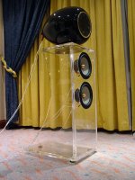
VPL is your answer, its easy to build and test it out and gives you the best of both worlds....The extended low end performance of deep sided U frames without the cuppy & boomy low midrange and bass (pipe resonance issues) and / or very wide front baffles.
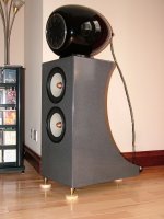
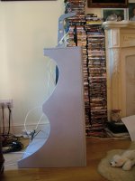
I have attached one example in two different materials ( acrylic and Corian) and I can post another more advanced version in MDF. to give you a visual example of the concept.
Its not rocket science, it just uses asymmetry to eliminate baffle step and path length cancellations.
The clue is in the name "baffle step" lets get rid of the "step" and make it a very gentle and variable "slope"...!
Imagine how the sound waves "see" the baffle as they radiate out from the front of the cone, spread out over and around the baffle, round the sides and are met by the sound waves coming out of the rear of the cone on their journey round the cabinet.
By taking "shark bites" out of the sides one can achieve various degrees of asymmetry therefore varying the actual baffle width (this dimension obviously includes the depth of the cabinet sides) that the sound waves "see"
One can even use different shapes for the left and right sides of each cabinet.
Taken to its logical conclusion one can use 4 different shapes of sides on each pair of speakers...This spreads any room interaction ( note interaction not just room...Earl!)
As I was selling commercial designs I balanced asthetics with performance...4 different sides did improve the performance but looked wrong!
Also you can use some Twaron / Angel Hair and various absorbers close behind the drivers and cover it with black grill foam...looks good and works great. Pic of that somewhere...I will post it later.
Anyway, hope this is of interest and you cut some sides and test it out.
All the best
Derek.
I can also say that a good DSP (DEQX is great, Mini DSP good) with Eq is marriage made in heaven with VPL designs.
Hi Beanbag,
VPL is your answer, its easy to build and test it out and gives you the best of both worlds....The extended low end performance of deep sided U frames without the cuppy & boomy low midrange and bass (pipe resonance issues) and / or very wide front baffles.
I have attached one example in two different materials ( acrylic and Corian) and I can post another more advanced version in MDF. to give you a visual example of the concept.
Its not rocket science, it just uses asymmetry to eliminate baffle step and path length cancellations.
The clue is in the name "baffle step" lets get rid of the "step" and make it a very gentle and variable "slope"...!
Imagine how the sound waves "see" the baffle as they radiate out from the front of the cone, spread out over and around the baffle, round the sides and are met by the sound waves coming out of the rear of the cone on their journey round the cabinet.
By taking "shark bites" out of the sides one can achieve various degrees of asymmetry therefore varying the actual baffle width (this dimension obviously includes the depth of the cabinet sides) that the sound waves "see"
One can even use different shapes for the left and right sides of each cabinet.
Taken to its logical conclusion one can use 4 different shapes of sides on each pair of speakers...This spreads any room interaction ( note interaction not just room...Earl!)
As I was selling commercial designs I balanced asthetics with performance...4 different sides did improve the performance but looked wrong!
Also you can use some Twaron / Angel Hair and various absorbers close behind the drivers and cover it with black grill foam...looks good and works great. Pic of that somewhere...I will post it later.
Anyway, hope this is of interest and you cut some sides and test it out.
All the best
Derek.
I can also say that a good DSP (DEQX is great, Mini DSP good) with Eq is marriage made in heaven with VPL designs.
Attachments
Suspended drivers
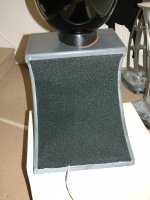
Last big upgrade was to not to bolt the drivers to the baffle...
Suspend them and ensure they are a "snug" but not tight fit...Use a thick internal Sorbothane or foam gasket and use wooden . Sorbothane foam gaskets to gently hold the drivers in place ....Works a treat and totally eliminates cabinet resonance. This is a big issue,
Cheers
Derek.
Attachments
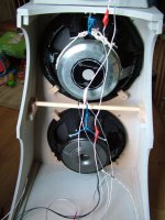
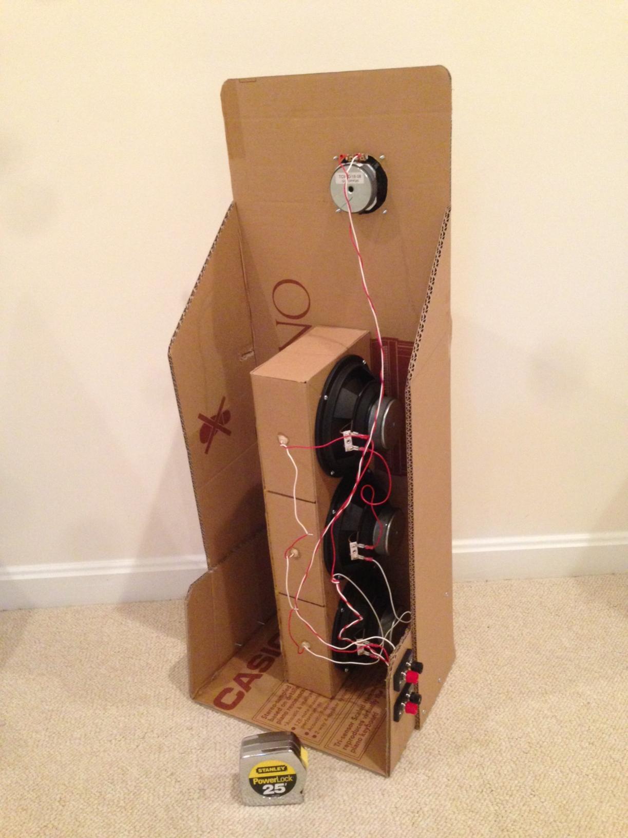
If a narrow OB array is your goal, take a look at a push-pull slot loaded open baffle in a U frame. The drivers are 90deg to baffle axis so they can be narrower. I have found that 6.5in dia woofers in this config can work very well. The quality of the bass is very good with clean dynamics and nice extension. My prototype is in cardboard but certainly you can make it out of wood.
Ztransform also came up with a similar design. There is not reason why you can't extend the height to make an array.
Here is link to my implementation.
http://www.diyaudio.com/forums/full-range/249984-cheap-fast-ob-literally.html
Ztransform also came up with a similar design. There is not reason why you can't extend the height to make an array.
Here is link to my implementation.
http://www.diyaudio.com/forums/full-range/249984-cheap-fast-ob-literally.html
Last edited:
Thanks for the replies.
For the VPL, is there some guideline for the longest vs shortest section? For example, it is twice as long so that the node of one resonance wave interacts with the anti-node of the other, or something like that?
For the slot loaded OB, I saw the gainphile page, where he mentioned that it had a resonance / long decay time due to the cavity. Is there some inherent problem with turning a sound wave 90 degrees in such a short distance?
I recently got the front panels for this laser cut out of MDF, in which all the drivers are forward facing. It actually has 5 holes, and yes, I know that I can't really wire up 5 woofers. So I am going to wire up 4 for now, and depending on how low the frequencies go, I will either add a 6th woofer as an attachment, or turn the bottom woofer into a sealed design.
This slot loaded version sounds very interesting, and I might save that idea for making a compact set of desktop speakers. (After I finish all my other projects, LOL)
Thanks for the replies.
For the VPL, is there some guideline for the longest vs shortest section? For example, it is twice as long so that the node of one resonance wave interacts with the anti-node of the other, or something like that?
For the slot loaded OB, I saw the gainphile page, where he mentioned that it had a resonance / long decay time due to the cavity. Is there some inherent problem with turning a sound wave 90 degrees in such a short distance?
I recently got the front panels for this laser cut out of MDF, in which all the drivers are forward facing. It actually has 5 holes, and yes, I know that I can't really wire up 5 woofers. So I am going to wire up 4 for now, and depending on how low the frequencies go, I will either add a 6th woofer as an attachment, or turn the bottom woofer into a sealed design.
This slot loaded version sounds very interesting, and I might save that idea for making a compact set of desktop speakers. (After I finish all my other projects, LOL)
You are not turning a sound wave 90 deg in case of bass freq - they are much longer. The slot will serve as a bandpass for HF and that is actually what you want to have happen in a woofer.
- Status
- Not open for further replies.
- Home
- Loudspeakers
- Multi-Way
- Asymmetric U frame open baffle?