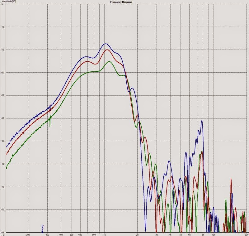
Here's some frequency response plots. I did these with Arta and measured in my living room with a very short gate. Due to the short gate the low resolution accuracy will be iffy. (Should be good above 500hz.) Each plot is at zero degrees (yellow), 22.5 degrees (orange), and 45 degrees (red)
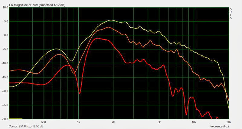
These are the horizontal polars. I'm running the horn flipped 90 degrees, so these polars will be different than what you see from other users. (Will be the same as their verticals.) In the graphs we see that the midrange is quite low, but this is due to the fact that I only have one midrange on the horn, not four. Once I add three more the level will rise by about six decibels. There's also an off-axis dip due to it being a dipole, and that peak is higher in frequency than the last horn because this horn is smaller.
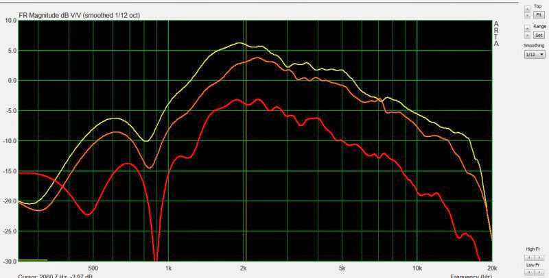
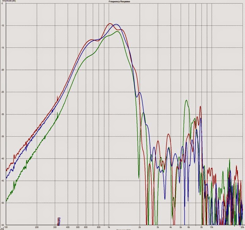
Here's the vertical polars. Same setup as the last graph, which is one compression driver and one midrange mounted on the horn. The dipole dip is a little bit lower in frequency because the horn is taller than it is wide.
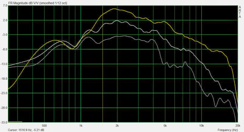
Here's where things get interesting. As I've noted on some other threads, I really like the sound of PK Sound cardioid subs, and the Gradient Helsinki cardioid. And I think that my Synergy horn will be cardioid-ish, not dipole or monopole. In the graph above, I have reduced the output of the midranges. I did this with a very sophisticated device.
I wrapped a wool scarf around the horn tightly
But this worked pretty good I think. Here's some advantages we see:
1) The cardioid-ish response is much smoother in the high frequencies. I believe this is because the scarf is reducing the output from the midranges, so that it doesn't interfere with the compression driver. The reason that we have to do this is because the front of the midranges is filtered by the coupling chamber and the horn, but the output radiating from the rear of the cones is unrestricted. And due to that, as you move off axis on the dipole, you get ripples in the response. Going cardioid cleans that up, as you can see in the off axis response particularly at 45 degrees.
2) Going cardioid-ish reduces the depth of the dipole dip around 900hz
3) On the downside, going cardioid-ish reduces the low frequency output level. (Because there are frequencies where the front and back combine constructively.) But this isn't a big deal, because we have tons of midrange output once we put four midranges on the horn.
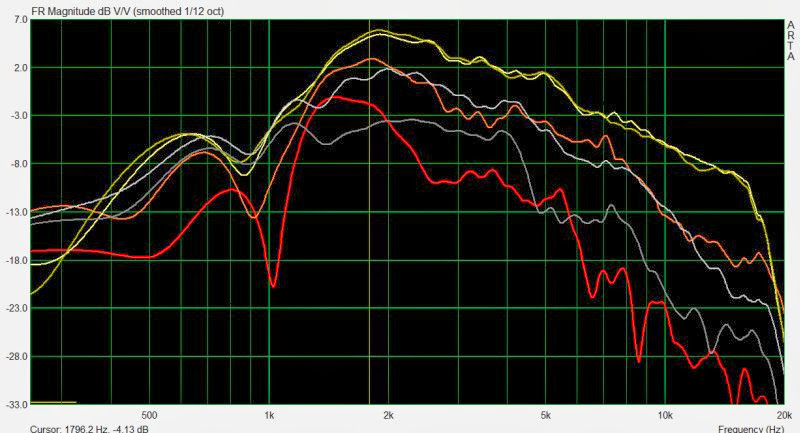
Here's the cardioid-ish response by itself, and on the same graph as the dipole for comparison's sake.
I had some excellent results with a cardioid-ish type speaker recently, so I decided to resurrect this *other* project that's been gathering dust in my garage.
If anyone wants to follow the progress, the post above details the speaker project named "Monster Massive", which is basically a Synergy horn midrange and tweeter, combined with a U-Frame woofer section. The use of a U-Frame raises the F3, but makes the speaker more directional.
I'll post some pics and measurements tonight.
If anyone wants to see how I got here, check out the thread http://www.diyaudio.com/forums/multi-way/264680-lx-mini-homage-2nd-try-2.html#post4129746
That's the speaker that I finished this month.

Here's what Monster Massive looked like before. It's in the center, between my Vandersteens and my Summas

Here's what it looks like now. Same woofer, different tweeter (Vifa XT25) and different waveguide (clone of JBL PT waveguide from Pyle)

Some pics of the speaker coming together
A polar response measurement of the tweeter on the waveguide (0, 22.5, 45degrees), with a simple first order low pass to offset the rolloff introduced by the CD waveguide.
Nice. What frequency are you planning on running the woofers down to?
I'm not sure yet.
John K uses a baffle width of about six inches. That width sets his crossover point to something like 1khz, due to the dipole peak.
Something I realized from my last project (http://www.diyaudio.com/forums/multi-way/264680-lx-mini-homage-2nd-try-2.html) was that you need to keep the width of that baffle narrow.
So the baffle width will likely set the crossover point. Hopefully I can get it down to something like 1khz.
It's hard to predict right now, because the radiation is complex. "The Edge" can sim a baffle, but I am not aware of anything that can easily sim a dipole waveguide.
TLDR: I'll probably run the 12" woofer from about 125hz to 1khz, the mids from 1khz to 2khz, and the tweeter from 2khz to 20khz

Hi Juhazi,
Windows are bad for medium-treble ! Does Audi maid a version with mdf windows-screens
Indeed, find the little unity horn maid by P.Batman fellow very smart ! Have you one for a Renault Clio... I puted Audax aerogel in mine and JM lab tweeter... but... well it's a bad trade off... this is the best choice for me as it was harder to putt wheels on my main Living Room speakers
@ Patrick : like all your "detournement" designs, huge and great DIY spirit ! I can write it as it was Thanksgiving yesterday !
Windows are bad for medium-treble ! Does Audi maid a version with mdf windows-screens
Indeed, find the little unity horn maid by P.Batman fellow very smart ! Have you one for a Renault Clio... I puted Audax aerogel in mine and JM lab tweeter... but... well it's a bad trade off... this is the best choice for me as it was harder to putt wheels on my main Living Room speakers
@ Patrick : like all your "detournement" designs
, huge and great DIY spirit ! I can write it as it was Thanksgiving yesterday !
Last edited:
This is a repost from Diyma, but the data is from this speaker, so here goes:
____________________________________________________________________
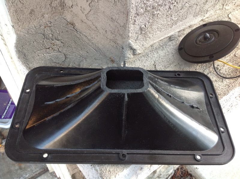
Here's some more measurements of a woofer with a coupling chamber in front of it.
This type of arrangement is handy if you're trying to cram the output of a 12" woofer through a 6" hole. For instance, if you have a 12" woofer in you're trunk, and you're hanging the woofer off of the rear deck and firing through the stock speaker hole.
In the world of horns we call this a "coupling chamber."
But you can use a coupling chamber with anything. A sealed box, a vented box, etc.
Basically the coupling chamber acts like an inductor, it rolls off the highs. The cool thing is that it's way WAY cheaper than an inductor, it reduces harmonic distortion, and it allows you to squeeze a lot of output through a small gap.
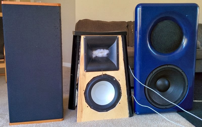
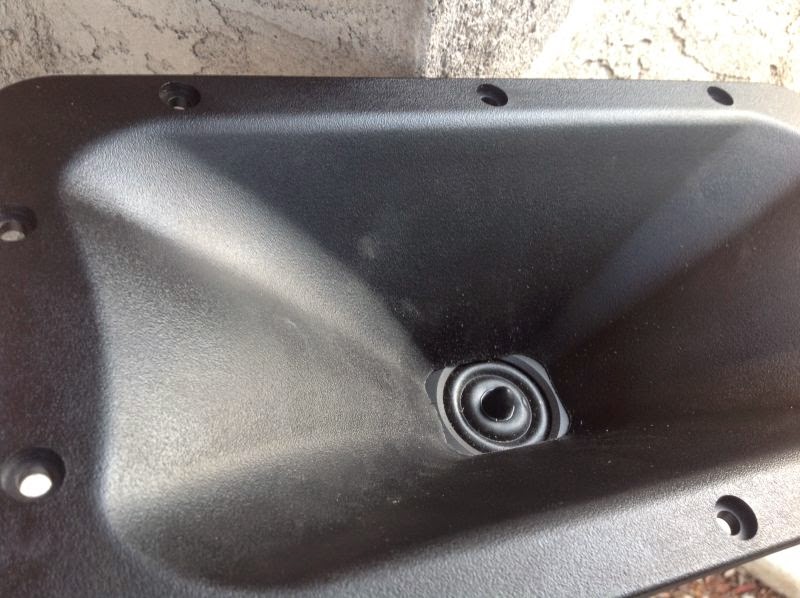
First off, here's a pic of what the speaker looked like before I added a coupling chamber. It's the speaker in the center, sporting a Diyma12, flanked by my Vandersteens and my Summas.

Here's the speaker with the coupling chamber in place. The coupling chamber crams the output of a cone that's about 11" in diameter through four holes that have a combined size of about 5". (It's actually four 2.5" holes, which is equivalent to ONE 5" hole.)
This is similar to what the prosound company "Nexo" uses in their loudspeaker arrays.
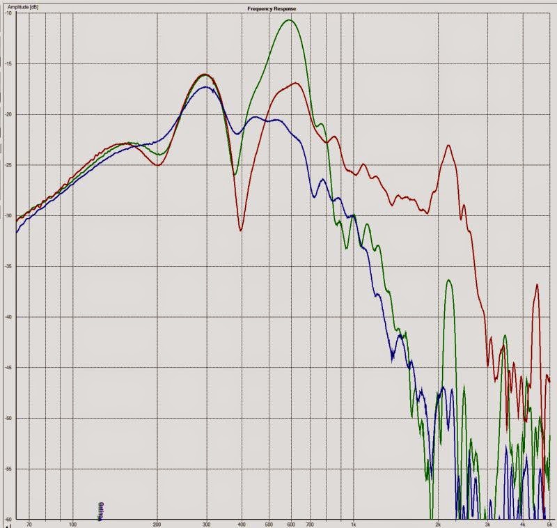
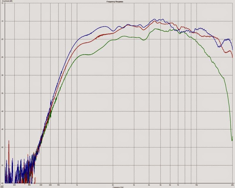
Here's the measured response. I did this in my living room, so there's going to be some reflections in the mix. IE, response won't be as smooth as you'd get with an outdoors measurement.
The red line is the DIYMA12 response with no coupling chamber.
Green line is with the coupling chamber.
The blue line is with the coupling chamber, and some fiberglass insulation inside the chamber.
Some observations:
1) The response of the DIYMA12 without a coupling chamber has a hell of a dip at 400hz. That dip limits it's usable upper limit to about 200hz, despite the fact that it has output out to 2khz. The dip is likely due to resonance in the cone or in the inverted dustcap. Basically, the cone is ringing.
2) The coupling chamber fills in the dip and rolls off the highs. But it also exaggerates the output at 600hz, by six dB.
3) The best solution, in this scenario, is to shove some fiberglass insulation into the coupling chamber. We lose a tiny bit of low frequency efficiency, about one decibel. But we smooth out the response in a HUGE way now.
I have an inductor in series with the Diyma in these measurements. If you tweaked the size of the inductor, and adjusted the fiberglass batting a bit, you could probably run the Diyma12 all the way to 1khz!
And THAT is why low inductance subwoofers rule!
____________________________________________________________________
Here's some more measurements of a woofer with a coupling chamber in front of it.
This type of arrangement is handy if you're trying to cram the output of a 12" woofer through a 6" hole. For instance, if you have a 12" woofer in you're trunk, and you're hanging the woofer off of the rear deck and firing through the stock speaker hole.
In the world of horns we call this a "coupling chamber."
But you can use a coupling chamber with anything. A sealed box, a vented box, etc.
Basically the coupling chamber acts like an inductor, it rolls off the highs. The cool thing is that it's way WAY cheaper than an inductor, it reduces harmonic distortion, and it allows you to squeeze a lot of output through a small gap.
First off, here's a pic of what the speaker looked like before I added a coupling chamber. It's the speaker in the center, sporting a Diyma12, flanked by my Vandersteens and my Summas.
Here's the speaker with the coupling chamber in place. The coupling chamber crams the output of a cone that's about 11" in diameter through four holes that have a combined size of about 5". (It's actually four 2.5" holes, which is equivalent to ONE 5" hole.)
This is similar to what the prosound company "Nexo" uses in their loudspeaker arrays.
Here's the measured response. I did this in my living room, so there's going to be some reflections in the mix. IE, response won't be as smooth as you'd get with an outdoors measurement.
The red line is the DIYMA12 response with no coupling chamber.
Green line is with the coupling chamber.
The blue line is with the coupling chamber, and some fiberglass insulation inside the chamber.
Some observations:
1) The response of the DIYMA12 without a coupling chamber has a hell of a dip at 400hz. That dip limits it's usable upper limit to about 200hz, despite the fact that it has output out to 2khz. The dip is likely due to resonance in the cone or in the inverted dustcap. Basically, the cone is ringing.
2) The coupling chamber fills in the dip and rolls off the highs. But it also exaggerates the output at 600hz, by six dB.
3) The best solution, in this scenario, is to shove some fiberglass insulation into the coupling chamber. We lose a tiny bit of low frequency efficiency, about one decibel. But we smooth out the response in a HUGE way now.
I have an inductor in series with the Diyma in these measurements. If you tweaked the size of the inductor, and adjusted the fiberglass batting a bit, you could probably run the Diyma12 all the way to 1khz!
And THAT is why low inductance subwoofers rule!
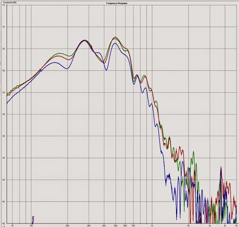
As noted in the previous post, I stuffed some fiberglass insulation into the coupling chamber. After doing that, here's the frequency response of the woofer with no filters. Green is on-axis, red is 22.5 off axis, blue is 45 degrees off axis.
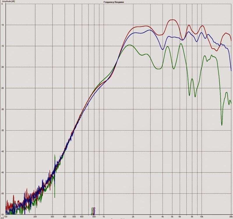
Here's the polars of the tweeter on the waveguide.
For comparison's sake, here's the same tweeter and waveguide before the four midranges were added to the horn. You can see that the midrange taps and the screws to fasten them are definitely having an effect on the frequency response. Oddly enough, the 22.5 degree polars on the waveguide with midrange taps is the smoothest. My hypothesis is that this is because the midrange taps create peaks and dips that are symmetrical; turn the speakers a bit and you mess up the symmetry of the taps. (Symmetry Horn?)
Here's the response of the midrange drivers. (four drivers.)
IIRC, this measurement is the response of the waveguide with just two midranges. This graph has some EQ on it. I found that increasing the number of midranges doesn't just raise the power handling and the efficiency, it also widens the bandwidth of the midranges and smooths out the response. Paul Spencer showed something similar on his blog "redspade audio."
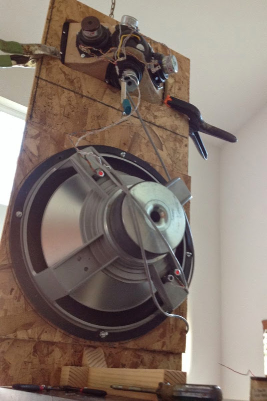
This is what Monster Massive looked like two days ago. It's a Synergy horn on top, with a DIYMA12 woofer at the bottom. The Diyma is in a U-Frame, the Synergy horn is a dipole waveguide.
An externally hosted image should be here but it was not working when we last tested it.
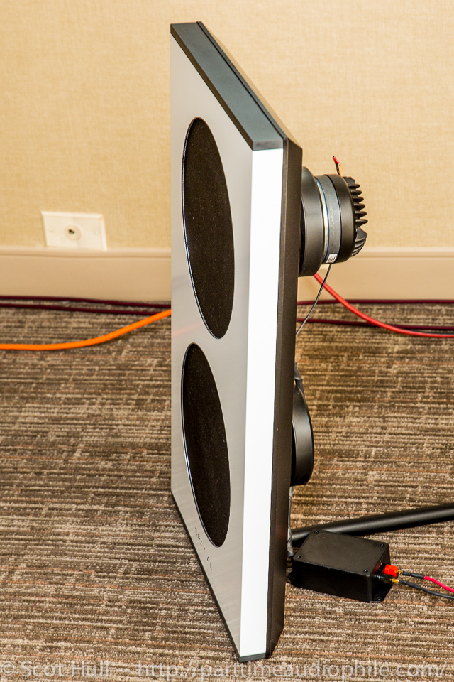
At T.H.E. Show in Costa Mesa, I thought the Spatial M2 sounded fantastic.

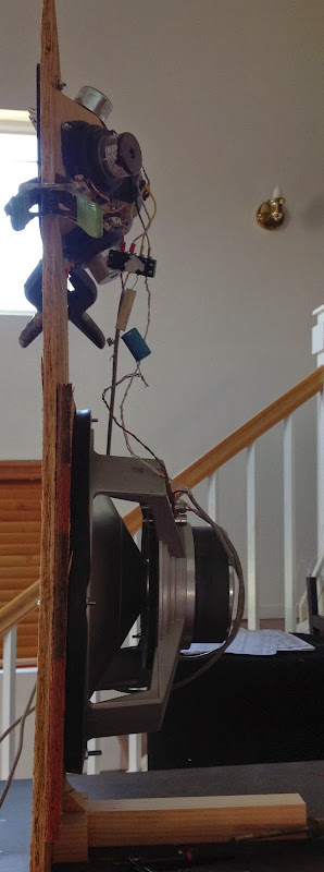

Inspired by Spatial and Emerald Physics, I stole a page from their playbook. The new Monster Massive uses a simple flat baffle, like the Spatial M2. It uses a 15" TC Sounds Dipole woofer for the woofer. The Synergy horn at the top is the same Synergy Horn I used before.
Here's some reasons I went with this:
1) They efficiency on the Diyma12 is very low. While it can handle a lot of power, I am using cheap amps and I don't have a lot of power on tap. Theoretically it's 4x100w, but I'm fairly certain the output isn't that high.
2) My TC Sounds dipole woofers are practically designed for this app.
3) My TC Sounds woofers were too large for the old Monster Massive cabinet, which was based on a 29" barstool sold at Wal Mart.
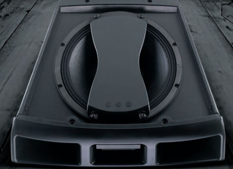
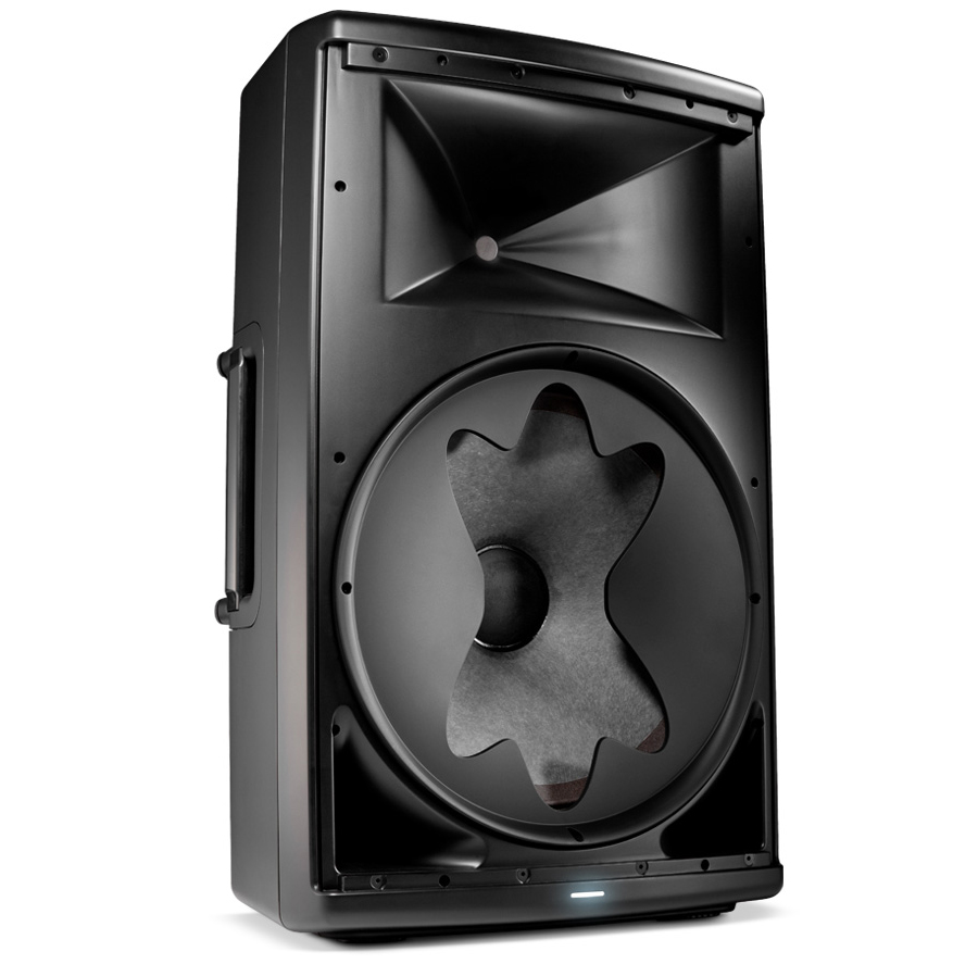
I see that mask as a way to widen horizontal response in the high end of the woofer. I guess that effect on spl and distortion is minimal.
More info http://www.jblpro.com/ProductAttachments/EON615_Datasheet_082014_CMYK.pdf
So, matching a 15" or 12" to a horn comes easier. Who will copy this first to diy?
More info http://www.jblpro.com/ProductAttachments/EON615_Datasheet_082014_CMYK.pdf
So, matching a 15" or 12" to a horn comes easier. Who will copy this first to diy?
It's not due to the SIZE of the waveguide, it's due to the SHAPE of the waveguide.
For instance, a 12" woofer will have symmetric polars at the xover. (This is because the cone is symmetrical.)
But a JBL PT waveguide won't. It's wider horizontally than it is vertically.
So the aperture widens the beamwidth of the woofer in the JBL EON, by changing it's acoustic size. It basically takes a 15" radiator and makes it behave like it measures about 7.5" wide.
Wish I'd seen this a week ago!
Then again, it wouldn't be too difficult to fill in those holes in my baffle...
Looks to me JBL turned a BR enclosure into a BP6 enclosure. Too bad they don't show the frequency response of the woofer by itself.
From page 13, here's the response of my woofer with no chamber, with a chamber, and with a chamber stuffed with fiberglass insulation.
I can see why JBL used a strange shape; when I used a simple circular hole I got a big ol' peak in the response. I nuked that peak with fiberglass but it cost me some output. Since the peak is caused by geometry, the irregular shape that they used makes sense.
If you model the woofer chamber and port CSA you will see that the peak is a function of the area and chamber volume. The smaller the CSA the higher the peak. You can reduce peak with smaller chamber by placing a shaped volume filler plug. The JBL shape probably has more to do with it acting as a diffractive acoustic lens to change the directivity to match the horn than it does to get the peak to be smaller. The CSA on the JBL port is so big there is probably no resonance peak.
I know a guy who did this in his car audio system in about 2005...he was sponsored by JBL.
I see that mask as a way to widen horizontal response in the high end of the woofer. I guess that effect on spl and distortion is minimal.
More info http://www.jblpro.com/ProductAttachments/EON615_Datasheet_082014_CMYK.pdf
So, matching a 15" or 12" to a horn comes easier. Who will copy this first to diy?
- Status
- This old topic is closed. If you want to reopen this topic, contact a moderator using the "Report Post" button.
- Home
- Loudspeakers
- Multi-Way
- Monster Massive