This is a report on my latest speaker project which has occupied most of my free time over the last six months. Since I am getting on in years, I expect this will be my last serious speakers, but I always say that. Typically I get about 10 years before the itch becomes intolerable and I have to scratch it again. Since my speakers are getting more massive as I get more feeble, this may well be it for me.
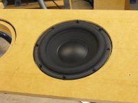
I went for top grade drivers, Scanspeak Tweeter D2904-710001, Scanspeak 6.5” Mid-Woofer Revelator 18W8531G00, twin Peerless 10” Woofers P830452. I want to crossover the mid quite low, around 150-180 Hz, so the mid has to have good power handling which is why I choose the 6.5” Revelator rather than the 5.5". This means the mid-treble crossover will be closer to 2 kHz than 3 kHz. I have plenty of choice with power amps since I have run active 3-ways for over 10 years now. I plan to run with 400 wpc into 4 ohms bass, 200 wpc into 8 ohm mid, 100 wpc into 8 ohm treble, so headroom is not a problem. I am a convert to active crossovers for equalization, time and phase alignment. The best way I can describe the benefits is that it is like when a camera image snaps into focus as the the focusing ring is adjusted. Once you have become used to a time and phase aligned speaker system, most passive crossover speakers sound vague and unnatural by comparison, especially on transients such as percussion, cymbals etc. I have found a well aligned speaker does a great job with reverberation and ambient sounds, which makes the stereo image very convincing, especially width and depth. Controlling edge diffraction is essential to obtain the benefits of good time and phase alignment. Drivers must be properly flush rebated and sharp enclosure edges removed (as shown by the classic Harry Olson paper (JAES November 1951). Here are the issues I have tried to address.
Enclosure features:
1. Constrained layer damped wall construction.
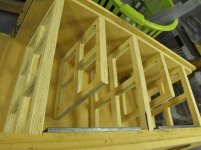
2. Rigid multiple 25 mm plywood braced enclosure walls.
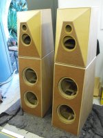
3. Separate bass enclosure to minimize interference and intermodulation.
4. Non-rectangular shape to control internal air resonances.
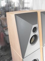
5. Angled edge to tweeter-mid section to optimize diffraction performance.
6. Massive cast resin angled tweeter-mid baffle.
7. Inner box separated from outer box by damping layer.
8. Bass drivers rigidly attached to inner box with no direct contact to outer layers.
9. Massive four layer mdf bass baffle.
10. Bass drivers attached to internal machined steel 10 mm threaded plates by machine bolts.
11. Marine ply outer stiffening layer.
Acoustical features:
12. Time aligned drivers.
13. Phase aligned drivers.
14. Active crossover.
15. Linear phase (Bessel) crossover alignment.
16. Critically damped sealed bass enclosure loading
17. Tri-amped configuration.
18. Equalised driver frequency bands.
19. Flat overall on-axis room frequency response.
20. Low distortion drivers.
21. High power handling drivers.
22. Wideband drivers.
23. Flush mounted drivers.
24. Felt damped tweeter-mid baffle.
I learned a lot during this construction. I am getting close to installing the drivers and performing the final testing/alignment/tuning process which I will perform with my measuring microphone, RTA and various test signal sources (including actual recorded music).
I went for top grade drivers, Scanspeak Tweeter D2904-710001, Scanspeak 6.5” Mid-Woofer Revelator 18W8531G00, twin Peerless 10” Woofers P830452. I want to crossover the mid quite low, around 150-180 Hz, so the mid has to have good power handling which is why I choose the 6.5” Revelator rather than the 5.5". This means the mid-treble crossover will be closer to 2 kHz than 3 kHz. I have plenty of choice with power amps since I have run active 3-ways for over 10 years now. I plan to run with 400 wpc into 4 ohms bass, 200 wpc into 8 ohm mid, 100 wpc into 8 ohm treble, so headroom is not a problem. I am a convert to active crossovers for equalization, time and phase alignment. The best way I can describe the benefits is that it is like when a camera image snaps into focus as the the focusing ring is adjusted. Once you have become used to a time and phase aligned speaker system, most passive crossover speakers sound vague and unnatural by comparison, especially on transients such as percussion, cymbals etc. I have found a well aligned speaker does a great job with reverberation and ambient sounds, which makes the stereo image very convincing, especially width and depth. Controlling edge diffraction is essential to obtain the benefits of good time and phase alignment. Drivers must be properly flush rebated and sharp enclosure edges removed (as shown by the classic Harry Olson paper (JAES November 1951). Here are the issues I have tried to address.
Enclosure features:
1. Constrained layer damped wall construction.
2. Rigid multiple 25 mm plywood braced enclosure walls.
3. Separate bass enclosure to minimize interference and intermodulation.
4. Non-rectangular shape to control internal air resonances.
5. Angled edge to tweeter-mid section to optimize diffraction performance.
6. Massive cast resin angled tweeter-mid baffle.
7. Inner box separated from outer box by damping layer.
8. Bass drivers rigidly attached to inner box with no direct contact to outer layers.
9. Massive four layer mdf bass baffle.
10. Bass drivers attached to internal machined steel 10 mm threaded plates by machine bolts.
11. Marine ply outer stiffening layer.
Acoustical features:
12. Time aligned drivers.
13. Phase aligned drivers.
14. Active crossover.
15. Linear phase (Bessel) crossover alignment.
16. Critically damped sealed bass enclosure loading
17. Tri-amped configuration.
18. Equalised driver frequency bands.
19. Flat overall on-axis room frequency response.
20. Low distortion drivers.
21. High power handling drivers.
22. Wideband drivers.
23. Flush mounted drivers.
24. Felt damped tweeter-mid baffle.
I learned a lot during this construction. I am getting close to installing the drivers and performing the final testing/alignment/tuning process which I will perform with my measuring microphone, RTA and various test signal sources (including actual recorded music).
Attachments

Last edited:

Looking good so far Bon. The 452s are nice in that they work in smaller boxes, but you might need an LT on them to get the extension you're after. They do give nice performance up higher then you'd usually get out of a sub driver, but crossing them around 150Hz is a good idea imo as it also lets you get the most out of the revelator mid. You might of course find that the system sounds even better crossed over even lower, but that's all a part of the fun once you get the drivers installed.
I used the 12" 830500 in my current speakers and they are equalised flat down to 25 Hz in a sealed enclosure. There are only a few suitable bass drivers with the required power handling and low distortion high excursion. It is a challenge though to find a bass amp with the balls to deliver the current. I have had plenty of reputable amps clipping or going into protection on high level bass transients. One good thing about going active is that bass clipping is does not make the whole sound stage collapse since the mid and treble are still clean. I try and avoid it though. It's not good for the amps. I have never detected the Peerless 830500 speaker in distress even when my bass clipping indicators are flicking on at 400 watt peaks.you might need an LT on them to get the extension you're after.
That is what I am thinking toobut crossing them around 150Hz is a good idea imo as it also lets you get the most out of the revelator mid. You might of course find that the system sounds even better crossed over even lower,
Attachments
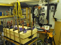
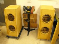
After many years of making do with the garage, I finally took the plunge and built myself a proper separate workshop. Then I seriously tooled up for woodworking. I have a very nice table mounted router, 12" compound sliding saw, deWalt vernier bench saw, small band saw, compressor, HVLP guns and lots more (especially clamps, you can never have too many). These speakers are my first big project with the new facilities. So I suppose I should add the cost of the shed and tools to the speaker costs😀Massive respect for your woodworking skills. Awesome!
Hi Bon,
having the right sort of space to work in, is essentially, something I can only dream about where I live. I am envious. I am a very creative person who has to make do with a minute amount of space to do what I wish too.
I hope this changes before I am to old and knackered.
having the right sort of space to work in, is essentially, something I can only dream about where I live. I am envious. I am a very creative person who has to make do with a minute amount of space to do what I wish too.
I hope this changes before I am to old and knackered.
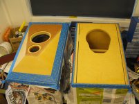
Hi David. The baffle of the tweeter-mid enclosure is a fibreglass (isopthalic) resin core inside a 25 mm mdf skin. I discovered the damping properties of resin a while ago, when investigating material for turntable plinths. For plinths the resin requires fibreglass ply re-inforcement for strength but for the baffle, the 25 mm mdf skins provide sufficient strength. The Audio Qualia site plinths - Audio qualia contains good information about the audio damping properties of various materials. I fabricated the baffle outer skin from mdf with compound mitre and table saw cuts. The outer skins were glued up with Selleys polyurethane glue. I chose this glue over PVA because of its space filling properties. Be careful with the vapours from polyurethane glue because it is isocyanate based, which has some bad potential health effects. (2-pac sprays are similarly dangerous to inhale or even absorb through the skin). I filled the underside of the glued up baffle over a couple of days (no more than 10 mm at a time, since the curing generates significant heat and this heat can affect the strength, cause cracks or even spontaneously combust). The final core is 90 mm thick at its deepest. The finished baffle is attached by compression of a layer of glazing silicone.Awesome work Bon!
Can you go into a bit more detail on how you made that cast resin baffle?
Attachments

The baffle gets glued to the enclosure under compression. The adhesive is Bostik V60 glazing silicone. The complete baffle is approximately 10 kg.Awesome work Bon!
Can you go into a bit more detail on how you made that cast resin baffle?
Attachments
I bow down before you great master.
When you die can I have your workshop, or at least the speakers.
I have about 2 decades left myself; I hope to leave behind something immovable to annoy my kids
When you die can I have your workshop, or at least the speakers.
I have about 2 decades left myself; I hope to leave behind something immovable to annoy my kids
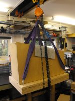
Well these certainly qualify. Part of the shed spec was a girder beam with block and tackle and I made good use of it.I hope to leave behind something immovable to annoy my kids
Attachments
Panel construction methods
I will describe the main principle and techniques I used for enclosures of this project. I wanted to attempt a constrained layer approach and build an enclosure where the outer layer was completely separated from the inner layer, with the bass drivers fixed to the inner layer with no mechanical contact with the outer box layers. Essentially a box within a box with a separating damping layer. I chose 18 mm mdf as the main box material to keep weight under control. I did some experiment with various damping layers. These are the constrained layers I tested:
1. PVA
2. Barium loaded vinyl 3 mm + contact cement
3. Rubber sheet 3 mm + contact cement
4. Sika polyurethane 3 mm
5. Bostik V60 glazing silicone 3 mm
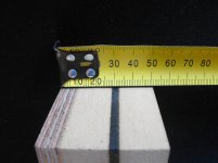
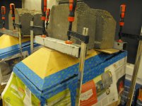
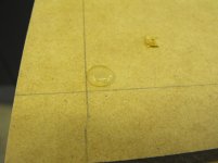
My objective test was to drop a steel ball from a fixed height onto the 30 x 30 cm constrained layer panels, firmly held down by lead blocks onto a concrete floor and also freely resting on supports above the floor. The rebound height of the ball was measured against a vertical scale. The lower the bounce, the more energy absorbed by the constrained layer. The rebound height varied over a 2:1 ratio from worst to best. The best was the Sika, closely followed by Bostik. The PVA glue was the worst. This panel was very stiff and gave off a distinctive “ping” that was slow to decay compared to the best. The good ‘ol knuckle rap was also revealing when carried out in open air. Unfortunately the Sika was far and away the most expensive material. The Bostik V60 was chosen for further evaluation, since I could get it at trade price through a contact. It is designed to hold large sheets of extremely heavy office glass windows in place under high wind loading and heat expansion. I tested a small sample for strength and the mdf failed rather than separating from the V60. As it turned out, the total cost of damping V60 used is twice the cost of the mdf.
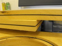
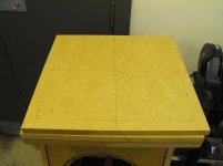
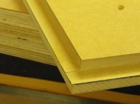
I prefabricated the rough trimmed enclosure panels in the following way. The idea is to spread the damping layer on the bottom mdf panel, then place a mdf panel on top, accurately located with pre-placed screws in oversized holes. The working time is short because the silicone loses its adhesive properties as it skins over. This is really a two person job because of the time limitations. You need to get that silicone on fast. Then the panel is compressed between two flat stiff surfaces with clamps until the required damping thickness is attained and there is significant ooze from all sides. To unsure the correct spacing, 3 mm adhesive silicone buttons are placed between the mdf in a regular grid. The silicone needs to cure for about 48 hrs before the clamps are removed. The cured overfill is trimmed off cleanly with a sharp blade. Later I will describe how I join the enclosure panels to separate inner and outer layers at the edges.
I will describe the main principle and techniques I used for enclosures of this project. I wanted to attempt a constrained layer approach and build an enclosure where the outer layer was completely separated from the inner layer, with the bass drivers fixed to the inner layer with no mechanical contact with the outer box layers. Essentially a box within a box with a separating damping layer. I chose 18 mm mdf as the main box material to keep weight under control. I did some experiment with various damping layers. These are the constrained layers I tested:
1. PVA
2. Barium loaded vinyl 3 mm + contact cement
3. Rubber sheet 3 mm + contact cement
4. Sika polyurethane 3 mm
5. Bostik V60 glazing silicone 3 mm
My objective test was to drop a steel ball from a fixed height onto the 30 x 30 cm constrained layer panels, firmly held down by lead blocks onto a concrete floor and also freely resting on supports above the floor. The rebound height of the ball was measured against a vertical scale. The lower the bounce, the more energy absorbed by the constrained layer. The rebound height varied over a 2:1 ratio from worst to best. The best was the Sika, closely followed by Bostik. The PVA glue was the worst. This panel was very stiff and gave off a distinctive “ping” that was slow to decay compared to the best. The good ‘ol knuckle rap was also revealing when carried out in open air. Unfortunately the Sika was far and away the most expensive material. The Bostik V60 was chosen for further evaluation, since I could get it at trade price through a contact. It is designed to hold large sheets of extremely heavy office glass windows in place under high wind loading and heat expansion. I tested a small sample for strength and the mdf failed rather than separating from the V60. As it turned out, the total cost of damping V60 used is twice the cost of the mdf.
I prefabricated the rough trimmed enclosure panels in the following way. The idea is to spread the damping layer on the bottom mdf panel, then place a mdf panel on top, accurately located with pre-placed screws in oversized holes. The working time is short because the silicone loses its adhesive properties as it skins over. This is really a two person job because of the time limitations. You need to get that silicone on fast. Then the panel is compressed between two flat stiff surfaces with clamps until the required damping thickness is attained and there is significant ooze from all sides. To unsure the correct spacing, 3 mm adhesive silicone buttons are placed between the mdf in a regular grid. The silicone needs to cure for about 48 hrs before the clamps are removed. The cured overfill is trimmed off cleanly with a sharp blade. Later I will describe how I join the enclosure panels to separate inner and outer layers at the edges.
Attachments

Rebate edge joints
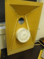
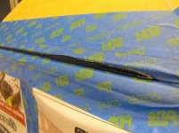
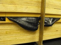
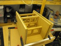
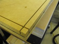
I chose to join the panels with full rebates the depth of an 18 mm mdf layer. This means trimming the edges down to the level of the damping layer. Each glue joint involves three surfaces joined with polyurethane glue. The rebating took a few tries to get a consistent result. I first tried using my table router but the amount of dust was discouraging since a lot of material is removed. Also the surface was slightly scalloped, not smooth enough for a good glue joint. So I used my table saw to remove a fillet by cutting two grooves at right angles. The depth and width of the table saw needs to adjusted quite precisely to cut just shy of the damping layer. I was content with about ½ mm clearance, which left a paper thin mdf layer attached to the silicone. If the blade does cut into the silicone, it tends to grab it and tear it out., which is something I wanted to avoid at all cost. Many trial cuts on scrap were needed to set up the table saw blade for each cut. I also needed to be very mindful of the panels staying tight to the fence, since I had only ½ mm to play with. Each rebate requires 2 cuts. The depth cut is straightforward since the panel is flat on the table. The 90 degree crosscut requires the panel to be on edge, running the blade parallel to the silicone but ½ mm shy. To hold the panel vertical I clamped it to an open-sided mdf box (a good use for a test speaker box that I cut up). I could then use the box as a jig to hold onto while guiding the vertical panel through the saw. I used polyurethane glue for the assembly because of its space filling properties and it will stick to anything. It is a bit messy but I just kept wiping away the excess foaming until it stabilized. Of course everything is clamped square while the glue dries. If you look at some of the pictures of the partially complete enclosures you can see the silicone layer around the edges. In most cases there is a damping layer between adjacent outer panels. Don’t get too excited about this though because I clad the whole mdf carcass with 9 mm marine ply later, which connects all the outer panels (but the inner panel are isolated by the continuous damping layer).
Next I will explain how I connect the bass drivers to the inner box, isolated from the outer box by a damping layer.
Attachments
Respect mate what a great build 😎🙂.
I've used SikaFlex in automotive applications ,great product .
Great idea with the overhead rail need to do this myself to take the load off from my back .
Keep the pic's coming .
Cheers
Mal
I've used SikaFlex in automotive applications ,great product .
Great idea with the overhead rail need to do this myself to take the load off from my back .
Keep the pic's coming .
Cheers
Mal
Bass baffle construction
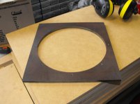
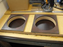
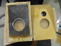
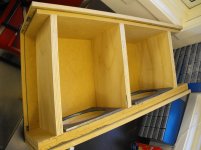
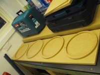
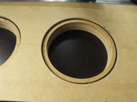
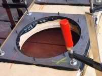
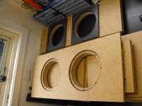
The bass baffle consists of three layers of 18 mm mdf plus an outer cosmetic layer of 4.8 mm Masonite (hardboard). The two inner layers are 18 mm mdf bonded with PVA glue.Then a third layer of 18 mm mdf was temporarily attached with wood screws. The centres for the bass drivers was located and locating pivot hole drilled for the circle router drilled though the three attached layers. Then I removed the temporary screws and using the router jig and a 6 mm router bit, cut the inner woofer holes through the double 36 mm mdf inner layer. Through the single 18 mm mdf layer I cut the outer woofer flange hole oversize by 6 mm radius. Then these outer holes sit over the woofer outer flange with 6 mm clearance all round. Now this outer layer is fixed to the double mdf layer by a damping layer. Using the same router jig settings and a sheet of 12 mm mdf, I cut rings with the same inner diameter. The ring outer radius is the width of the blade smaller than the larger holes in the outer layer. I glued these rings with PVA to the inner double layer concentric with the holes. The woofer flanges sit on these rings, rebated by 6 mm (18-12). (Since the final masonite layer adds 4.8 mm, the woofers are rebated approx 11 mm from the final baffle surface). Finally the outer layer is attached to the inner layers plus rings by a damping layers. I applied the silicone with the press and clamps as described previously, with a grid of spacing buttons. The temporary screw holes were re-used to line everything up. I clamped the layers together in the press so that the silicone oozed up into the 6 mm gap between the mdf rings and the outer layer, as well as from the edges. Enough silicone was used to ensure a proper overfill. The excess was trimmed off at the end of a 48 hr curing period. Excess silicone is much more easily removed after curing. Any attempt to clean up before then results in a hellacious mess.
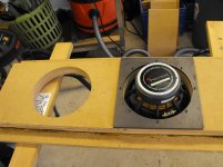
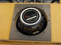
Finally I attached 10 mm steel plate to the inside of the baffle with silicone under extreme clamping. I am of the opinion that it is almost impossible to achieve long term secure woofer fixing with the usual t-nuts and the like. The problem being the mdf these fixing are attached to. So as an extreme solution, I obtained 10 mm plasma cut interior plates with threaded 5 mm holes. I plan to be careful not to crack the woofer frame with the hardened steel bolts I use. Bought myself a torque wrench for security. 😀
The bass baffle consists of three layers of 18 mm mdf plus an outer cosmetic layer of 4.8 mm Masonite (hardboard). The two inner layers are 18 mm mdf bonded with PVA glue.Then a third layer of 18 mm mdf was temporarily attached with wood screws. The centres for the bass drivers was located and locating pivot hole drilled for the circle router drilled though the three attached layers. Then I removed the temporary screws and using the router jig and a 6 mm router bit, cut the inner woofer holes through the double 36 mm mdf inner layer. Through the single 18 mm mdf layer I cut the outer woofer flange hole oversize by 6 mm radius. Then these outer holes sit over the woofer outer flange with 6 mm clearance all round. Now this outer layer is fixed to the double mdf layer by a damping layer. Using the same router jig settings and a sheet of 12 mm mdf, I cut rings with the same inner diameter. The ring outer radius is the width of the blade smaller than the larger holes in the outer layer. I glued these rings with PVA to the inner double layer concentric with the holes. The woofer flanges sit on these rings, rebated by 6 mm (18-12). (Since the final masonite layer adds 4.8 mm, the woofers are rebated approx 11 mm from the final baffle surface). Finally the outer layer is attached to the inner layers plus rings by a damping layers. I applied the silicone with the press and clamps as described previously, with a grid of spacing buttons. The temporary screw holes were re-used to line everything up. I clamped the layers together in the press so that the silicone oozed up into the 6 mm gap between the mdf rings and the outer layer, as well as from the edges. Enough silicone was used to ensure a proper overfill. The excess was trimmed off at the end of a 48 hr curing period. Excess silicone is much more easily removed after curing. Any attempt to clean up before then results in a hellacious mess.
Finally I attached 10 mm steel plate to the inside of the baffle with silicone under extreme clamping. I am of the opinion that it is almost impossible to achieve long term secure woofer fixing with the usual t-nuts and the like. The problem being the mdf these fixing are attached to. So as an extreme solution, I obtained 10 mm plasma cut interior plates with threaded 5 mm holes. I plan to be careful not to crack the woofer frame with the hardened steel bolts I use. Bought myself a torque wrench for security. 😀
Attachments


Yes, it is extreme. I had trouble just lugging the baffle alone around the workspace. I glued up the baffle with the same silicone that is used for the constrained layers. So steel+silicone+mdf is another constrained layer. The layer of silicone is as thin as I could make it by clamp pressure. It is as dead as a doornail. Not a peep. Kaput. I was concerned though about the effect of steel on the magnetic field of the woofer magnet. I had an email conversation with the audio consultant for WES Components, the supplier of my drivers who designs subs using these woofers. He was ok with the my application. The steel is not that close to the magnet.That is one serious front baffle... Do you expect any ringing from the steel plate?
Attachments
Makes the use of "T-Nuts" look a little wimpy.
I have to ask; what the heck are you going to be using as the sub-woofer for those boxes??
I have to ask; what the heck are you going to be using as the sub-woofer for those boxes??
I am of the opinion that it is almost impossible to achieve long term secure woofer fixing with the usual t-nuts and the like.
I don't have much faith in t bolts as well ,the metal their made from and the thread flights seem weak. If I was to use them after testing of the system I would use a medium thread lock and spring washes .
Cheers
- Status
- Not open for further replies.
- Home
- Loudspeakers
- Multi-Way
- 3-way active, time aligned, constrained layer construction