Hi,
In my hunt for a vintage alnico speaker, for a small valve amp project, a colleague has kindly offered the speaker from his 'old' guitar amp which was scheduled for disposal.
On plugging and testing the amp before dismantling it, I was confronted by hum, hiss, sizzle and apart from immediately powering off, only lots of turning of the volume, treble and bass knobs revealed the following:
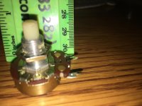
-treble and bass pots had absolutely no effect on the audio output, or if it did
it was not audible to me.
-the volume pot only worked to about 3 o'clock and the amp went quiet thereafter.
-slow turning of the volume pot could locate a 'sweet spot' where the output was clean and with an almost valve like presence.
Unplugging and removing the chassis was straightforward, so I immediately got to work replacing the pots, using what I had in my spare parts bin, after which very little sonic improvement was achieved.
Since the markings on the chassis indicated assembly date as being '1973-or 1978' the last digit is not clearly visible) -I recapped the board - replacing all the electrolytics, which was a relatively cheap and affordable exercise.
The amp sounded good after the recap - but the little else changed re; volume, treble bass and output noise.
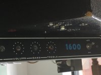
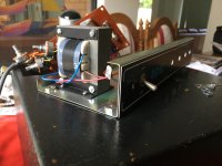
I do not have schematics for this amp which is identified as a Made In New Zealand Alron 1600 50watt guitar amp.
If anyone has the schematic, experience, information or any suggestion to help rejuvenate this piece of vintage equipment, it would be appreciated as I would love to retain this amp as a backup.
Thank you.
In my hunt for a vintage alnico speaker, for a small valve amp project, a colleague has kindly offered the speaker from his 'old' guitar amp which was scheduled for disposal.
On plugging and testing the amp before dismantling it, I was confronted by hum, hiss, sizzle and apart from immediately powering off, only lots of turning of the volume, treble and bass knobs revealed the following:
-treble and bass pots had absolutely no effect on the audio output, or if it did
it was not audible to me.
-the volume pot only worked to about 3 o'clock and the amp went quiet thereafter.
-slow turning of the volume pot could locate a 'sweet spot' where the output was clean and with an almost valve like presence.
Unplugging and removing the chassis was straightforward, so I immediately got to work replacing the pots, using what I had in my spare parts bin, after which very little sonic improvement was achieved.
Since the markings on the chassis indicated assembly date as being '1973-or 1978' the last digit is not clearly visible) -I recapped the board - replacing all the electrolytics, which was a relatively cheap and affordable exercise.
The amp sounded good after the recap - but the little else changed re; volume, treble bass and output noise.
I do not have schematics for this amp which is identified as a Made In New Zealand Alron 1600 50watt guitar amp.
If anyone has the schematic, experience, information or any suggestion to help rejuvenate this piece of vintage equipment, it would be appreciated as I would love to retain this amp as a backup.
Thank you.
Circuitry
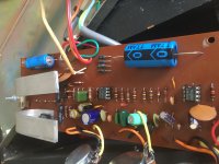
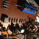
Yes - it is a solid state amp - I overlooked, but should have mentioned that. I have in the past hour of backtracking realised that I have removed the two opamps from the pcb and installed adaptors.
The preamp section had a resistor across pins 2 and 6 of the opamp, which I removed together with the opamps when I installed the. I have resoldered the rsistor and now I am back to amplified sound being produced when I plug in a guitar.
But as per my original post - still wooshing sound from volume pot and full range of volume pot not accesible.
I could not attach pics - it use to be simpler but now I am asked to provide a url???
Last edited:

I'd strongly suggest you prepare a sketch of the circuitry, along with measured DC operating voltages, and post - it doesn't need to be neat and tidy, and as there is not much circuitry in that amp it should be fairly easy to fault-find, depending on what test equipment you have (?).
You definitely need to repair that amp - even if it is just to show off the heatsinks!
You definitely need to repair that amp - even if it is just to show off the heatsinks!
")
??? sketch the circuitry?? I wouldn't know where to start! Although considering the current status of the country - and the world it might prove to be a constructive activity worth undertaking. If only i knew how.
I have a dvm, capacitance tester- oscilloscope that I havent used for years!
Its a great piece of vintage electronics IMHO, even though it is not a 'boutique' name brand!
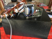
The case is made of mdf - sealed with a heavy duty coat of paint that gives the box an almost seamless appearance.
And even after all these years, no scratches, dings or dents can be seen, although the unprotected corners show the wear that is consistent with its age.
And the heatsinks!!!! mmm! I was impressed by the creativity. A few years ago my son-in-law asked me to check his faulty subwoofer. I narrowed the fault down to an inadequate heatsink, so I bent a strip of aluminium into a U screwed it to the main heatsink and fastened the chip to the strip.
it is still working nearly 5 years later! Reminds of an old saying:'Great minds think alike - but Fools seldom differ'
Some of the local stuff from that era is really quite nicely made, all done by hand of course, and usually more or less "borrowed" circuit designs from imported models. I've a lovely Sonophone mk III here which needed basically nothing done and it's all original, it's a great little 20 odd watt stereo amp. Worth the effort imo to trace out the circuit, then some expert on here can probably spot the problem right away. It's not too hard to do, just start somewhere and track what's connected to what until you've mapped it all out. A meter helps (on buzzer mode if it has one). Then measure voltages from gnd/0v when it's on (carefully, insulate most of the dmm probe leaving only the tip). Good project for level 4 lockdown [emoji1787]
Yeh, probably not the best time to ask around for anyone with a bit of electronics experience to come over and sketch the circuit for you.
If you do get brave enough, perhaps just start with the signal in from the guitar jack and identify the first few parts. Do the same for the speaker connection back in to the amp circuitry. And do the same for the power supply rectifier and filter, and see what connects to the dc supply rails.
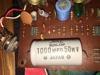
With your meter you could start by measuring the DC voltage across the 1000uF first filter cap, and see if your meter also has an AC voltage range and use that to check the AC voltage across that capacitor. The voltage across that capacitor is your main voltage supply rail, with the positive rail passing through the fuse and then to one side of the output stage transistors, and the negative rail going to the other side of the output stage. The other large electrolytic cap is your speaker output coupling cap, so it should have a DC voltage on its positive terminal that is half the main supply DC voltage (with reference to the main 0V supply) - that would be the first simple check to make.
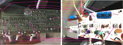
You can check the voltage across pins 7 to 4 on the 741 IC's, where pin 4 is connected to the 0V main supply rail (if you follow the pcb trace through).
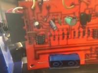
The photo also looks like you have soldered pin 6 to 7 on the 741 IC with the resistor attached to the rear - that would connect the opamp output (pin 6) to the positive supply rail for the opamp - not what is expected I think!
The datasheet for the 741 opamp is http://www.ti.com/lit/ds/slos094g/slos094g.pdf
If you do get brave enough, perhaps just start with the signal in from the guitar jack and identify the first few parts. Do the same for the speaker connection back in to the amp circuitry. And do the same for the power supply rectifier and filter, and see what connects to the dc supply rails.
With your meter you could start by measuring the DC voltage across the 1000uF first filter cap, and see if your meter also has an AC voltage range and use that to check the AC voltage across that capacitor. The voltage across that capacitor is your main voltage supply rail, with the positive rail passing through the fuse and then to one side of the output stage transistors, and the negative rail going to the other side of the output stage. The other large electrolytic cap is your speaker output coupling cap, so it should have a DC voltage on its positive terminal that is half the main supply DC voltage (with reference to the main 0V supply) - that would be the first simple check to make.
You can check the voltage across pins 7 to 4 on the 741 IC's, where pin 4 is connected to the 0V main supply rail (if you follow the pcb trace through).
The photo also looks like you have soldered pin 6 to 7 on the 741 IC with the resistor attached to the rear - that would connect the opamp output (pin 6) to the positive supply rail for the opamp - not what is expected I think!
The datasheet for the 741 opamp is http://www.ti.com/lit/ds/slos094g/slos094g.pdf
Last edited:
Alron 1600
I double checked the opamp, the resistor is soldered between pins 2 and 6.
My Sanwa dvm has both AC and DV, an old piece of test equipment given to me by an electrical engineer.
I read an article somewhere about using a grid method to analyze and trouble shoot sections of a pcb - never thought I would ever need to use it, maybe now is a good a time as any!
Thanks for the motivation - this is going to take some time....watch this space.
Attachments
Possible oscillation due to dried out decoupling capacitors? Sudden changes in behaviour
when gain is changed are usually the onset or ceasation of ultrasonic oscillations.
Are the decoupling capacitors visible in the attached pics?
??? sketch the circuitry?? I wouldn't know where to start! ...
If it was all on one side, you'd just follow the wires and note the parts along the way.
On PCB, it helps if you can hold it up to the light so you see the parts and the shadows of the traces.
When that is difficult, you can try photographing (or scanning) both sides and flop one over the other. Some trickery to drop-out background helps.
Then draw out the map.
It does help to have lots of experience reading both schematics and PCBs. I've read many thousand schematics. Like a football quarterback, when I see players in certain configurations I get a good idea what they want to do.
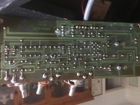
Though in this case, much is clear from miles away. It's a guitar amp! It has an input jack, goes through passive parts to a preamp chip. Then some tone control parts (and pots) to a booster amp. It claims 50 Watts and those funky bent aluminum things on power transistors is part of that. We see ma huge(?) main power cap, and the four diodes commonly used to turn PT AC into DC.
Attachments

Hi PRR, I have been following your posts and sound advice (excuse the pun), for years now. Specifically relating to cd player modifications and power supply and clock upgrades. So I have a little experience reading schematics and PCBs.
Anyway, I took your advice and gave it a go - but not before walking away and thinking about what resources are available to me.
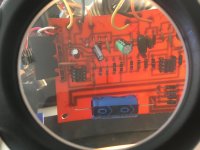
I found a PCB holder, an old desktop halogen lamp, soldering station and LED magnifier.
And this is what the setup looks like ;-)
Anyway, I took your advice and gave it a go - but not before walking away and thinking about what resources are available to me.
I found a PCB holder, an old desktop halogen lamp, soldering station and LED magnifier.
And this is what the setup looks like ;-)
Attachments
Update!
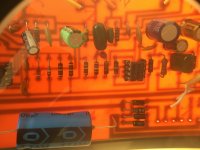
Ok, this is as far as I managed to go.
Above the location of the opamp, is a 1uf 50v electrolytic . It has a 5mm pitch and the solder pads are closely spaced on the pcb. I realised that some solder had bridged the gap between the pads!!!
I heated, and removed the bridge and cleaned up the solder. Connected all wires to the board, plugged my guitar in found it to sound really nice and clean throughout the volume pot rotation. Treble and bass works as well- although not as prominently.
Now wondering if I should still proceed with the schematic for future reference or move on to my valve amp project waiting in the wings???
This is one old lady that is NOT going to the garbage. Thanks guys for the inspirational advice and suggestions, all are greatly appreciated.
Attachments
- Status
- This old topic is closed. If you want to reopen this topic, contact a moderator using the "Report Post" button.
- Home
- Live Sound
- Instruments and Amps
- 1970's Vintage New Zealand Alron rejuvenate