Not sure if this is the right place to post but has anyone actually tried the SIDEGIG-GUITAREVM from Texas Instruments?
Here is the evaluation board
http://www.ti.com/tool/SIDEGIG-GUITAREVM
And it plugs into the TPA3255 Class-D amlifer
http://www.ti.com/tool/tpa3255evm
I am wanting to build a Bass amplifier and want to base my whole design around the TPA3255 amp and use the SIDEGIG design as my preamp and overdrive circuit but I am worried it might not sound as good as I want it to.
Has anyone tried it out yet?
If I posted in the wrong section please let me know where I should post...
It will work, but nothing in that circuitry is earth shatteringly new as far as guitar preamps go. You mentioned using it for bass guitar, and one thing that a lot of solid state bass amps have is some compression/limit stage right before the power amp section.
You could have a look at the Fender Rumble series for ideas , it's patented but basically the output speaker signal level is detected and fed back to an OTA between the preamp and the power amp. You may be able to do something similar with a simple optical type compressor/limiter.
Thanks for the reply man! Do you by any chance know any reference designs for a compression/limit stage?
The ne plus ultra is the Engineer's Thumb by ValveWizard.
Last edited:
It’s made to add distortion like a drive pedal or similar, specifically for electric guitar. Of course one could add pedals before it for more or different effects.For guitar use, it might sound too clean, OTOH.
Best regards!
I got one of these and a TPA3255EVB back when TI was running a 50% off sale on their EVB's. It is all opamp based except for a BJT buffer on each input. The schematic is in the user manual (top link in first post). There are "two channels," but unlike many two channel guitar amps the dirty "drive" channel feeds into the clean channel in a manner much like a distortion pedal. It uses dissimilar LED's in the feedback path of an opamp for asymmetrical clipping. The clean channel has a volume control on the input, so it will do a very clean guitar sound at speaker smoking volume levels when used with the 3255 board and the switch in the "clean" position In dirty mode the volume control on the guitar has a big effect on the distortion level.
I used this with the TPA3255 board to shred a couple of crappy speakers and generally make a racket when connected to a pair of EVM-10M guitar speakers. I have never been a fan of super distorted solid state amps, but this was not as bad as some commercial amps I remember from my past.
I then wired it up to a push pull tube amp based on a Tubelab SSE board since the SideGig has the phase splitter built in so the SE tube amp could drive a push pull OPT for a 50 watt amp. The clean channel was rather nice sounding, but the SideGig has enough output to push a pair of 6L6GC's well into distortion for a nice tube distortion sound.
I never tried playing bass through either combination, but I do believe that some compression might be needed if for no other reason than keeping the cones in your speakers if you tend to slap the strings around.
This is a three year old thread, so I'm not sure if the OP is being helped in any way by recent posts.
However, George's post made me curious, so I looked up the schematic.
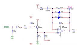
There are many disappointing things about it, but one that hits like a hammer blow is the weirdly inept input stage: a low-beta emitter follower, with a disappointingly low input impedance, placed in front of an op-amp that would do a far better job on its own, without the dumb BJT follower.
Datasheet current gain for the transistor used (2N4401) is as low as 40 at 1 mA collector current, which is roughly the operating point used in the Sidegig. Input impedance, as seen by the guitar, is an unacceptably low 189 kilo ohms in this case.
Use of the 4558 op-amp at the input is another head-scratcher. If a JFET-input op-amp had been used here, the poorly functioning BJT emitter follower could then have been ditched, with R15 raised to 1 Meg.
Alternatively, the BJT buffer could have been fixed by simply using a better transistor, one with a current gain that doesn't have a 12.5:1 range of production spreads (!!!) A BC 550C would have done the trick, with a few other changes - bias the base from the +12V rail rather than the 0V rail, which would have allowed a much higher-value bias resistor, and input impedance.
A JFET at the input would have been even simpler. With a (-12V) rail available, biasing the JFET becomes trivial: wire the gate to ground via a 1 meg input resistor, wire the source to the (-12V) rail with, say, a 15k resistor, done.
The surprisingly poorly executed design continues elsewhere. Look at the differential output stage. There are two unity-gain inverting stages, one after the other. The output of the second stage, therefore, is identical to the input to the first one!
What's more, that input signal is already buffered by a preceding stage. This means U3B, and all the circuitry around it, is utterly useless. The exact same signal could have been taken straight from the output of U2B (output of U3B is identical to U2B).
Then we come to the subtler failings. The clean channel is "too clean" for guitar, i.e., it will produce sterile, cold, thin, Hi-Fi sounds. Meantime, the drive channel is "too dirty", with typical aggressive diode clipping. And the designers didn't even put in a sprinkling of reverb or delay to help smooth out the harsh distortion, and add some life to the sterile clean tones.
In a nutshell: the Sidegig is exactly the sort of design that has given solid-state guitar amplifiers a (deservedly) terrible reputation for decades.
Bass guitars might be a different story. Many have onboard preamps and powerful EQ, so the failings of the BJT input stage are not so bad. Many bass players don't use any external distortion at all, so the "too clean" clean channel might not be a problem.
I'm barely beyond beginner level on a bass, and I hate slap-bass, so I play with two fingertips and traditional big fat round tone. So take my opinions for what they're worth. That said, I've made home recordings with and without compressor on the bass, and IMO it is easy to squeeze the life out of a track if you put just a wee bit too much compression on the bass guitar.
-Gnobuddy
However, George's post made me curious, so I looked up the schematic.
There are many disappointing things about it, but one that hits like a hammer blow is the weirdly inept input stage: a low-beta emitter follower, with a disappointingly low input impedance, placed in front of an op-amp that would do a far better job on its own, without the dumb BJT follower.
Datasheet current gain for the transistor used (2N4401) is as low as 40 at 1 mA collector current, which is roughly the operating point used in the Sidegig. Input impedance, as seen by the guitar, is an unacceptably low 189 kilo ohms in this case.
Use of the 4558 op-amp at the input is another head-scratcher. If a JFET-input op-amp had been used here, the poorly functioning BJT emitter follower could then have been ditched, with R15 raised to 1 Meg.
Alternatively, the BJT buffer could have been fixed by simply using a better transistor, one with a current gain that doesn't have a 12.5:1 range of production spreads (!!!) A BC 550C would have done the trick, with a few other changes - bias the base from the +12V rail rather than the 0V rail, which would have allowed a much higher-value bias resistor, and input impedance.
A JFET at the input would have been even simpler. With a (-12V) rail available, biasing the JFET becomes trivial: wire the gate to ground via a 1 meg input resistor, wire the source to the (-12V) rail with, say, a 15k resistor, done.
The surprisingly poorly executed design continues elsewhere. Look at the differential output stage. There are two unity-gain inverting stages, one after the other. The output of the second stage, therefore, is identical to the input to the first one!
What's more, that input signal is already buffered by a preceding stage. This means U3B, and all the circuitry around it, is utterly useless. The exact same signal could have been taken straight from the output of U2B (output of U3B is identical to U2B).
Then we come to the subtler failings. The clean channel is "too clean" for guitar, i.e., it will produce sterile, cold, thin, Hi-Fi sounds. Meantime, the drive channel is "too dirty", with typical aggressive diode clipping. And the designers didn't even put in a sprinkling of reverb or delay to help smooth out the harsh distortion, and add some life to the sterile clean tones.
In a nutshell: the Sidegig is exactly the sort of design that has given solid-state guitar amplifiers a (deservedly) terrible reputation for decades.
Bass guitars might be a different story. Many have onboard preamps and powerful EQ, so the failings of the BJT input stage are not so bad. Many bass players don't use any external distortion at all, so the "too clean" clean channel might not be a problem.
I'm barely beyond beginner level on a bass, and I hate slap-bass, so I play with two fingertips and traditional big fat round tone. So take my opinions for what they're worth. That said, I've made home recordings with and without compressor on the bass, and IMO it is easy to squeeze the life out of a track if you put just a wee bit too much compression on the bass guitar.
-Gnobuddy
Attachments
To begin with:
* it has a schematic error which makes it unusable: Tone Control capacitors C14 and C15 are 10X too small.
* it is unabashed copy of a Tube Screamer distortion pedal and a similar, very plain vanilla "clean preamp" (with wrong tone control values)
* single bipolar transistor buffer is a straight ripoff of Boss pedals, all include some variation of it.
Justified there because it provides unity gain buffered, low impedance signal for the effect ON/OFF footswitch, not needed here because no footswitch is used.
Just by sheer chance (or not?) it´s very very similar to my simplest Guitar Amp preamp, go figure

EDIT:you might consider building Rodd Elliott´s Guitar preamp ... which also works well on Bass, it has that old Fender Blackface/Silverface Bass sound.
Or as close as possible going full SS into Class D.
Even the very mild saturation/distortion it includes works well for a raw gritty Bass sound, great for Punk, Hardcore and even Metal.
* it has a schematic error which makes it unusable: Tone Control capacitors C14 and C15 are 10X too small.
* it is unabashed copy of a Tube Screamer distortion pedal and a similar, very plain vanilla "clean preamp" (with wrong tone control values)
* single bipolar transistor buffer is a straight ripoff of Boss pedals, all include some variation of it.
Justified there because it provides unity gain buffered, low impedance signal for the effect ON/OFF footswitch, not needed here because no footswitch is used.
Just by sheer chance (or not?) it´s very very similar to my simplest Guitar Amp preamp, go figure
EDIT:you might consider building Rodd Elliott´s Guitar preamp ... which also works well on Bass, it has that old Fender Blackface/Silverface Bass sound.
Or as close as possible going full SS into Class D.
Even the very mild saturation/distortion it includes works well for a raw gritty Bass sound, great for Punk, Hardcore and even Metal.
Last edited:
Look again. U3A has a gain of (-1). U3B also has a gain of (-1). They cancel each other out.Not true. U3B has flipped U3A's phase 180 degrees.
The output of U3B is identical to the output of U2B. That makes U3B utterly useless.
If not clear yet: you can get exactly the same differential outputs by using the output signals of U2B, and U3A.
U3B is as useful as a jello vaulting-pole.
-Gnobuddy
Not exactly re using U2B. Unity gain yes but he's looking for a roll-off above ~700KHz. Besides that -1 x -1 = +1 so the two U3 outputs are now a differential pair aka balanced with the same freq response behavior.Look again. U3A has a gain of (-1). U3B also has a gain of (-1). They cancel each other out.
The output of U3B is identical to the output of U2B. That makes U3B utterly useless.
If not clear yet: you can get exactly the same differential outputs by using the output signals of U2B, and U3A.
U3B is as useful as a jello vaulting-pole.
-Gnobuddy
My friend, that's a hundred times too high to matter. There's nothing good from an e-guitar at 7 kHz, never mind 700 kHz!...he's looking for a roll-off above ~700KHz.
U2B and U3B have identical output over (and far beyond) the frequency range of any guitar ever made.
The only difference is a little added noise at the output of U3B, along with a wasted op-amp, a few wasted passive components, and some wasted PCB real-estate. That's not an improvement.
U3B is a complete waste of an op-amp. When you also consider the rest of the blunders in the design, it all adds up to clear evidence of uninformed and poorly thought-out engineering throughout this particular preamp. IMO, whoever designed it preamp didn't know what he/she was doing.
-Gnobuddy
I think we have to be very kind and charitable to assume there was any kind of good reason.Maybe they saw some over-shoot or oscillation - who knows.
Occam's razor: "Entities should not be multiplied beyond necessity". Rather than assuming some uber-complicated good reason for this design, IMO it's more plausible that the person who designed it didn't really know what they were doing.
Maybe he/she was just having a really bad day (and continued to have a long string of bad days all the way through the design, prototyping, and production processes).
To me, the bottom line is very simple: this doodad isn't worth buying. Nor is it worth copying.
-Gnobuddy
- Home
- Live Sound
- Instruments and Amps
- Sidegig Guitar EVM from Texas Instruments thoughts?