Have you tried playing with LTSpice? It's free, and you can learn a lot by building and simulating virtual circuits.
On the other hand, playing with LTSpice also allow noobs like me to work-out an schematic an have their curves look like your plots, but without any actual knowledge about the system.
Oh hi, let me introduce myself. I am a bass player with and I love toying with electronics. Last year (oooh, remember last year when we could still have gigs and such
 ) I hacked myself a 2 channel tube pre-amp overdrive with 4 more fx loops using relays. (I still need to document this thing somewhere).
My plan is to place this preamp after the tubes of my TL-Audio 5051 (MK1) compressor, but before its XLR out. Meaning I can go straight to a console without needing a DI. The 5051 runs its tubes on 160V and i found commercial solutions for an FX loop either requiring 250V+ or receiving a lot of complaints. Luckily I found you guys here.
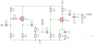
I managed to recreate the circuit posted here in LTSpice. Then I also managed to get the simulation running in KiCad. I'm attaching the KiCad project here so the next hacker does not need to go through this process again
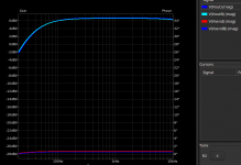
Okay, so as i started out with; I managed to nearly recreate your plot by changing two values.
First I changed to voltage to 160V, because that is what I have to work with. Then I increased the value for R22 (R22 because i copied the schematic to plot 2 voltages at the same time) to 110K to match the plot.
KiCad made this way to easy with a little slider i could draw until the lines overlapped. I would really like some feedback whether i'm making a sensible modification here.
Attachments
My take is that a lowered barrier to entry (easy LTSpice or Kicad fiddling) might encourage someone to learn more. The same person might be discouraged entirely if they had to learn college-level mathematics and study hybrid-pi transistor models before they could even begin to study the circuit they're interested in.On the other hand, playing with LTSpice also allow noobs like me to work-out an schematic an have their curves look like your plots, but without any actual knowledge about the system.
Hopefully, the start you made with Kicad will whet your appetite for more knowledge.
But yes, the very old saying "A little knowledge is a dangerous thing", is still quite true!
So far, so good. What happened is that lowering the DC supply voltage, also reduced the AC voltage gain of the recovery stage a little bit. Your tinkering found one way to bring the voltage gain back up to the original way. Again, good.First I changed to voltage to 160V
<snip>
I managed to nearly recreate your plot by changing two values.
But are there negative consequences? Is there a better way? Do we even need to tweak the gain back up by that tiny amount? Those questions can only be answered once you've learned a bit more.
(The answers are "Yes", "Yes", and "Not really" respectively. More on that in a moment.
Then I increased the value for R22 (R22 because i copied the schematic to plot 2 voltages at the same time) to 110K to match the plot.
Good question!I would really like some feedback whether I'm making a sensible modification here.
The first part of the answer is that 160 V DC is still plenty for a solid-state FX loop, provided you design and use the circuit appropriately.
The second part of the answer is that when you dropped the supply voltage from 300 to 160, that change screwed up the intended bias point of the second MOSFET (the gain recovery stage). That's not good.
The screwd-up bias point, in turn, will affect how much signal this recovery stage can handle before it clips. Depending on how badly the bias point was messed up, and how much output voltage you want from the circuit, premature clipping might be a problem. It might even be a very big problem.
How to answer those questions? With your Kicad sim, of course!
First, you need to tweak (increase) R20, until the gate of Q4 is back to around +18 to +20 V DC. Since you've roughly halved your supply voltage, you'll find you need to roughly double R20 to achieve this. Kicad will tell you when you're close enough - and make sure you pick a value of R20 that is actually available! You can easily buy 150k, 180k, 200k, or 220k, for example; but if Kicad simulation suggests you should use 199.32k, that is not a practical value (you can't buy it, and you don't need it).
Having changed R20 to a sensible value, now use Kicad to look at the DC voltage at the drain of the second MOSFET (Q4). This should be in the vicinity of +90 volts DC, plus or minus, say, 20 volts.
But it probably won't be, because you've halved the DC supply voltage.
You can fix this by changing the value of R21. You can make small tweaks to R22 if necessary, but I suggest starting with R22=100k, as I originally intended. With R22 set to 100k, then tinker with R21 in Kicad until Q4's drain is at around +90 volts DC, plus or minus 20 volts.
If you can't get there with any reasonable off-the-shelf value of R21, then, and only then, tinker with the value of R22 a wee bit to get the voltage where you want it.
At this point, Q4 is sensibly biased, and this will guarantee you lots of output headroom.
However, AC gain will probably not be what you want.
If you look at the LTSpice image I posted (post #25), you'll notice I wrote "Adjust R4 for AC gain" on the image. All the resistors in your KiCad redrawn circuit have different numbers - for the circuit you drew in Kicad in post #41, the relevant resistor is R23.
So your final step is to tweak R23 until you get the voltage gain you want/need from the circuit.
Note that you may or may not want exactly the same voltage gain I originally designed for. This depends on the rest of the circuit in your amplifier, and how much signal voltage it wants from Q4.
-Gnobuddy