I've been working on my high gain build for a few months now, and have gotten to a point where it's time to add an FX loop. And as such, I've been considering ways to reduce signal levels that would play nice with pedals. I'm guessing somewhere around 1Vpeak, probably even a bit less.
The natural place for me to get a starting point is proven designs.
Soldano uses a split cathode (from a DC coupled CF) to drop signal. That seemed pretty simple, effective and low parts count. But, I'm not using a CF in my build. So I gotta figure another way.
Then I figured I could just use a large voltage divider after the tone stack (say 1M/10k or whatever) to drop the signal down and then feed that into an AC coupled CF as an output buffer. The return would be a normal common cathode stage with a volume pot feeding the PI. That can work, but parts count is a bit high and requires an extra triode stage (output buffer).
Here's the thing, my preamp uses 5 stages. So ideally I'd use the unused triode in V3 as the FX return recovery stage.
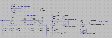
Then I got to thinking about split loads, similar to how the SLO does it. Except that instead of split cathode, how about split plate load? The signal voltage coming off V3a (final preamp stage) is upwards of 120VAC. According to my calculations, a 560ohm resistor would drop the signal down to about 700mV. And the output impedance would roughly be 560ish ohms, right? Seems like a win-win and uses minimal parts.
I've attached a snippet describing what I propose.
The question I have, is there anything I'm not considering? I don't think I've ever seen a design do it this way... I just wanted a bit of reassurance, one way or another.
P.S. I'm driving two 6V6's, so the loss from the tone stack isn't an issue.
EDIT: Schematic shows V4b, which should be V3b. Excuse the typo.
The natural place for me to get a starting point is proven designs.
Soldano uses a split cathode (from a DC coupled CF) to drop signal. That seemed pretty simple, effective and low parts count. But, I'm not using a CF in my build. So I gotta figure another way.
Then I figured I could just use a large voltage divider after the tone stack (say 1M/10k or whatever) to drop the signal down and then feed that into an AC coupled CF as an output buffer. The return would be a normal common cathode stage with a volume pot feeding the PI. That can work, but parts count is a bit high and requires an extra triode stage (output buffer).
Here's the thing, my preamp uses 5 stages. So ideally I'd use the unused triode in V3 as the FX return recovery stage.
Then I got to thinking about split loads, similar to how the SLO does it. Except that instead of split cathode, how about split plate load? The signal voltage coming off V3a (final preamp stage) is upwards of 120VAC. According to my calculations, a 560ohm resistor would drop the signal down to about 700mV. And the output impedance would roughly be 560ish ohms, right? Seems like a win-win and uses minimal parts.
I've attached a snippet describing what I propose.
The question I have, is there anything I'm not considering? I don't think I've ever seen a design do it this way... I just wanted a bit of reassurance, one way or another.
P.S. I'm driving two 6V6's, so the loss from the tone stack isn't an issue.
EDIT: Schematic shows V4b, which should be V3b. Excuse the typo.
Attachments
Last edited:
You might just skip the CF, and send the signal direct from the 10k resistor. True, 10k source impedance wouldn't be acceptable in modern studio practice, but it is just fine for any guitar FX that was originally designed to be fed from a guitar with a 250k volume pot. 10k is low enough not to pick up a lot of hum and interference, 10k is low enough not to suffer from "tone suck" with a reasonable length of shielded cable. In short, 10k is fine!Then I figured I could just use a large voltage divider after the tone stack (say 1M/10k or whatever) to drop the signal down and then feed that into an AC coupled CF as an output buffer.
")
The catch is that the 560 ohm resistor will have one end connected to B+ voltage....instead of split cathode, how about split plate load?
In principle, you can capacitor-couple the signal end of the 560 ohm resistor to your FX send, with a pull-down resistor to remove the huge DC voltage. But: (1) The FX send line might glitch all the way up to B+ voltage at turn-on, before the coupling cap is charged, and (2) Any hum or ripple on the B+ line is fed directly to your FX send, with no attenuation at all.
Here's another possibility: what if you break R46 into two, say a 1k resistor and 560 ohm resistor in series, with the 560 ohm resistor wired to ground? Then wire C28 to only bypass the 1k resistor, and not the 560 ohm one. Now take your FX send signal from the "hot" end of the 560 ohms.
Because there is about 650 - 700 ohms of cathode impedance "inside" the half-12AX7, the signal across the 560 ohm resistor will be about half as big as the signal at V4b's control grid. This probably won't exceed 2Vpp as the triode will either cutoff, or enter positive grid current territory if driven harder than that. I would say 2Vpp is a safe signal level to send to your FX loop, not big enough to do damage.
-Gnobuddy
Good points, thank you. I didn't draw in components for send/return jacks (still learning LTSpice), but yea C38 would decouple and the return path connected to R48/R104.
The early Mesa Boogie FX loops were just crude plate fed voltage dividers (unbuffered). I have a Studio Preamp (I think from '86 or so); and holy crap is the loop is a tone suck. I'm definitely avoiding that lol.
I actually tested the cathode output (R46) because it's basically the required voltage. I didn't split like you suggested though. However, I noticed severe HF loss so I dismissed it. I'll give that another look. Thanks for the tips.
Me too. I've been tinkering with it for a couple of years, but just this last week, I learned a few new tricks. It's an amazing piece of software!...still learning LTSpice...

Any chance you know what value resistors were used to divide down the signal? I wouldn't have thought a 10k source impedance would cause "tone suck" with most FX pedals, though anything is possible with ancient germanium-transistor effects....holy crap is the loop is a tone suck...
I have a Joyo compressor, which appears to be a clone of a Ross compressor, which itself appears to be pretty much identical to an MXR Dynacomp. At any rate, this compressor "tone sucks" like crazy if I plug a guitar straight into the input - weird, because that's exactly how you're supposed to use a compressor! So if I want to use it, I have to buffer the guitar with something else before the compressor.
I'm very curious what happened there. I would not have expected that. The cathode is the lowest impedance you'll get from a tube stage, and it should have been around 700 ohms there (assuming a half-12AX7.)...cathode output...severe HF loss...
-Gnobuddy
Any chance you know what value resistors were used to divide down the signal?
Here is a link to the Mesa SP schematic. Although I misspoke... while the FX Loop is 'colored' for sure, the Main outputs are even worse. I used to own a Mark IV, and the overdrive was super tight and crisp. The SP is more or less the same preamp (the first 5 or 6 stages), but has a certain "haziness" about it. After looking at the schematic I see why... the couple extra gain stages / coupling circuits step all over the tone.
The cathode is the lowest impedance you'll get from a tube stage
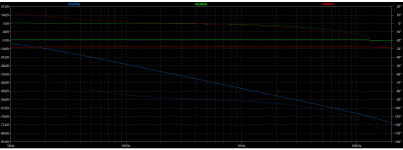
Yea, I dunno. Just did a quick spice sim, and it appears if the cathode is bypassed the HF is doodoo. Unbypassed it's A-Ok (for guitar amps). Split bypass produced a similar curve ~6dB lower. Sooo, it seems if one can live with the stage unbypassed, it's a viable option for a low imp send at "pedal" levels. For free!
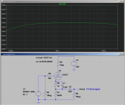
Attached is the response of all 3 on the same plot. Yellow is unbypassed, blue is fully bypassed (22uF) and red is split. (BTW, is there a way to turn off phase angles? would be clearer that way)
At any rate, this compressor "tone sucks" like crazy if I plug a guitar straight into the input
I know this is besides the point, but I learned early on in my guitar playing career to use the least amount of stuff between the instrument and the amp. And pretty much for that reason. To use one thing, you gotta have another thing to make it work. Not to mention forgetting something or losing/having gear stolen at a gig. Although, I can't live without a delay pedal. Hence why I needs a loop.
Attachments
Thanks for the link. A quick glance gave me a quick headache (Unbuffered FX sends, LC filters before the recording outputs??). I'll have to look at that at more length later.Here is a link to the Mesa SP schematic.
That is a very strange result, and doesn't match anything I know about electronics, either theory or experiment. I suspect the SPICE model you're using for the 12AX7 is (severely!) flawed....a quick spice sim, and it appears if the cathode is bypassed the HF is doodoo. Unbypassed it's A-Ok (for guitar amps).
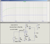
I ran the same simulation, and got very different results - take a look at the screenshot. Ruler-flat response out to 20 kHz, with or without a cathode bypass cap.
Incidentally, I used an LTSpice trick to get bypassed and unbypassed plots on the same graph: {Rbyp} is inserted in series with the bypass capacitor, and the Spice command ".step param Rbyp 1m 1Meg 1Meg" steps Rbyp between 1 milli-ohm and 1 mega-ohm.
When Rbyp is 1 mega-ohm, the bypass capacitor is effectively removed from circuit, and does nothing.When it's 1 milli-ohm, its so small that it has no effect, and the cathode is fully bypassed.
I'm attaching a screenshot, as well as the LTSpice sim file (.asc), and the 12AX7 model I used (12AX7.txt) Feel free to tinker with the .asc and .txt files if you like.
Yes there is! Mouse over the right vertical axis (the one with the phase angles), you'll see the cursor change into a small vertical ruler. Then left-click. A window will pop up, titled "Right Vertical Axis", with various options below. Click on "Don't Plot Phase", and the phase plots disappear from the graph.(BTW, is there a way to turn off phase angles? would be clearer that way)
I started out that way, but lately I'm going in the opposite direction. We all know of guitarists with wonderful tone who plug straight into their amp, and also guitarists with wonderful tone who use a slew of pedals - David Gilmour, for instance, or Eric Johnson. So we have demonstrated proof that you can have great tone either way.I know this is besides the point, but I learned early on in my guitar playing career to use the least amount of stuff between the instrument and the amp.
Yeah, I have a Moor Re-echo and a cheapy Biyang reverb on all the time. Also a graphic EQ pedal I use to dial in my basic clean tone. The reverb and delay are set for a pretty subtle effect, not in-your-face, but it adds a lot to the tone.I can't live without a delay pedal.
-Gnobuddy
Attachments
> I used an LTSpice trick to get bypassed and unbypassed plots on the same graph: {Rbyp} is inserted in series with the bypass capacitor, and the Spice command ".step param Rbyp 1m 1Meg 1Meg" steps Rbyp between 1 milli-ohm and 1 mega-ohm.
Another trick is to draw it once, copy/paste a second copy of the stage, mod that, and plot both outputs. Messy, but especially good when a variant is less trivial. I've had six BJTs and six different plots in one sim.
Another trick is to draw it once, copy/paste a second copy of the stage, mod that, and plot both outputs. Messy, but especially good when a variant is less trivial. I've had six BJTs and six different plots in one sim.
That's what I've been doing, only because I don't know any better. Gnobuddy's way is neater, for sure.Another trick is to draw it once, copy/paste a second copy of the stage, mod that, and plot both outputs. Messy, but especially good when a variant is less trivial. I've had six BJTs and six different plots in one sim.
That is a very strange result, and doesn't match anything I know about electronics, either theory or experiment. I suspect the SPICE model you're using for the 12AX7 is (severely!) flawed.
I ran the same simulation, and got very different results - take a look at the screenshot. Ruler-flat response out to 20 kHz, with or without a cathode bypass cap.
You're taking the output reference from the coupling cap (labeled vout). I'm talking about taking the output directly off Pin 2 of the triode (decoupled, of course). Remember, I'm trying to find the easiest and most transparent way to knock down the signal voltage for FX.
I tested it again, in spice and real-world: Unbypassed the frequency response = input, bypassed the HF plummets. I'm no EE, but I'm curious as to why. Or perhaps I'm missing something / doing it wrong?! IDK.

Apology for not seeing your 3-peat sim. Just like I would do, except being a cheap SOB I might use one battery and one sig-source.
I don't know what went wrong on V(n078); or which circuit IS V(n078). IMHO a schematics tool should have user-world labels on nodes.
It is *quite* odd that your plots show 7dB gain?? Or is that -7dB, and the pointless phase-plots are confusing me? (In circuits like this, we can know the phase from the slope of amplitude; anyway we do not care.) I not some other folks set .AC source amplitude to 0.1V; IMHO this is not-right. .AC analysis does not "overload", it assumes perfectly linear forever. Setting the source to 1V allows instant read-off of voltage gain re:1V. (Anyway my old sim won't take any other value.)
Plotting past the audio band adds hints. We see that all three forms have same gain at 100KHz, with similar slope. So the one with highest gain "must" start to fall sooner.
1Meg is probably an unrealistic load. Going into another hi-gain 12AX7 the grid capacitance acts-like 200K by 8KHz. Going to an external effect the cable capacitance is larger and the input may be 50K.
...spice sim, and it appears if the cathode is bypassed the HF is doodoo. ...
I don't know what went wrong on V(n078); or which circuit IS V(n078). IMHO a schematics tool should have user-world labels on nodes.
It is *quite* odd that your plots show 7dB gain?? Or is that -7dB, and the pointless phase-plots are confusing me? (In circuits like this, we can know the phase from the slope of amplitude; anyway we do not care.) I not some other folks set .AC source amplitude to 0.1V; IMHO this is not-right. .AC analysis does not "overload", it assumes perfectly linear forever. Setting the source to 1V allows instant read-off of voltage gain re:1V. (Anyway my old sim won't take any other value.)
Plotting past the audio band adds hints. We see that all three forms have same gain at 100KHz, with similar slope. So the one with highest gain "must" start to fall sooner.
1Meg is probably an unrealistic load. Going into another hi-gain 12AX7 the grid capacitance acts-like 200K by 8KHz. Going to an external effect the cable capacitance is larger and the input may be 50K.
Attachments
1Meg is probably an unrealistic load. Going into another hi-gain 12AX7 the grid capacitance acts-like 200K by 8KHz. Going to an external effect the cable capacitance is larger and the input may be 50K.
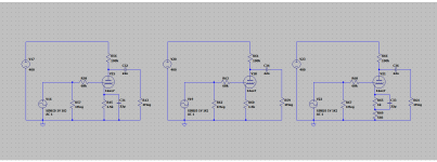
That's a single input stage copied x3. They're not intended to be cascaded. Sorry if it's confusing.
I was demonstrating, while taking the signal from the cathode (as a cheap way to get a low gain signal for FX send), the effect on HF gain a bypass cap has. When bypassed, the HF tanks.
Pin 2 is the control grid, a very high impedance point. Surely you're not trying to take an FX send from there?I'm talking about taking the output directly off Pin 2 of the triode (decoupled, of course).
Did you perhaps mean pin 3, the cathode? And is this the same cathode you were connecting directly to ground with a bypass cap? If so, then yeah, you were putting a big fat capacitor directly across the "send" signal, so of course treble would disappear.
Could you post the actual schematic you're using, along with an LTSpice label where you're taking your output signal from? If I could see exactly what you're doing, I could probably figure out what's going on.I tested it again, in spice and real-world: Unbypassed the frequency response = input, bypassed the HF plummets.
We'll get you your FX loop yet!
-Gnobuddy
I'm one of the guilty parties there. LTSpice clearly shows input overload when you do a transient sim, why on earth would it not do the same thing when you do a frequency response? Quite counter-intuitive, so I did not expect that rather bizarre behaviour....some other folks set .AC source amplitude to 0.1V
<snip>
.AC analysis does not "overload", it assumes perfectly linear forever.
So my approach has always been to use a 1V input for purely passive circuits (RC networks, etc), and for opamp circuits which I know are linear at that signal level. For anything else (diodes / BJTs / JFETS / tubes), I use a much smaller input signal, sufficiently small for the device to be well within its linear region in a .tran(sient) simulation.
What I want most from LTSpice at the moment is sane graph scaling. It wants to autoscale with the most unreadable increments (steps of 83mV each, for instance). The only fix I know of is to manually scale, save plot settings, and then recall plot settings on every subsequent re-run of the simulation. Tedious, and error-prone. Anyone know a better fix?
-Gnobuddy
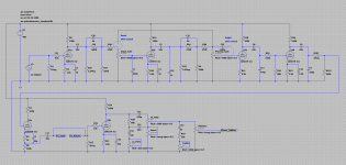
In the meantime, how's this look? (Pic attached)...let me tidy up my working schematic...
Output is -30 dBV for a -20dBV input, meaning output is roughly one-third of the input signal to the grid. In this case, 100 mV peak in, and roughly 30 mV peak out.
So if you want 100 mV RMS out (typical FX pedal level), you'll want roughly 1V peak-to-peak into the grid of the triode.
The 10uF coupling cap is to maintain low source impedance (at the FX send) down to the lowest guitar frequencies.
Fully bypassing a half-12AX7 doesn't take anywhere near as much capacitance as Leonidas used. In fact, 2.2 uF is actually all you need to move the bass cutoff frequency (-3 dB) well below the lowest note you can get from a guitar.
-Gnobuddy
Attachments
Yes, I understood that was 3 isolated stages.
But in most work the output of a stage goes someplace, usually less than 1Meg.
> I updated my schematic to reflect this change.
OK, now the lower cathode resistor is 560K; it was 560r before.
560K pull-down is a pretty weak stage.
And if you want a cathode follower, what is the 100K in the plate lead doing for you? It generally degrades performance.
Do you even need gain (voltage OR current) here?
OK, now the lower cathode resistor is 560K; it was 560r before.
560K pull-down is a pretty weak stage.
And if you want a cathode follower, what is the 100K in the plate lead doing for you? It generally degrades performance.
Do you even need gain (voltage OR current) here?
Don't think too much into it; merely a typo. Suppose to be 560Ω
Thanks for the schematic!Don't think too much into it; merely a typo. Suppose to be 560Ω
How about R7? I assumed earlier that you were going to be using a signal from V3a anode (as well as the FX send signal from V3a cathode.) I thought maybe your plan was to have a parallel FX loop or something like that.
But, as PRR says, if you are not going to be using a signal from the anode, then you can leave R7 out. Leaving out R7 will give V3a less input capacitance as there will be no Miller effect from the anode. This might be a good thing as V3a is being fed from a fairly high source impedance (R103 in parallel with R107), and therefore you want input capacitance low to make sure you have enough bandwidth.
One possible concern about removing R7 is that you will then have the full B+ voltage on the anode of V3a. If you're really feeding 400V DC to the 12AX7, this might be a concern. The datasheets I've looked at specify 300V maximum.
-Gnobuddy
Thanks for the schematic!
How about R7? I assumed earlier that you were going to be using a signal from V3a anode (as well as the FX send signal from V3a cathode.) I thought maybe your plan was to have a parallel FX loop or something like that.
But, as PRR says, if you are not going to be using a signal from the anode, then you can leave R7 out. Leaving out R7 will give V3a less input capacitance as there will be no Miller effect from the anode. This might be a good thing as V3a is being fed from a fairly high source impedance (R103 in parallel with R107), and therefore you want input capacitance low to make sure you have enough bandwidth.
One possible concern about removing R7 is that you will then have the full B+ voltage on the anode of V3a. If you're really feeding 400V DC to the 12AX7, this might be a concern. The datasheets I've looked at specify 300V maximum.
-Gnobuddy
V3a is being heavily overdriven, and is intended as a common cathode stage.
- Status
- This old topic is closed. If you want to reopen this topic, contact a moderator using the "Report Post" button.
- Home
- Live Sound
- Instruments and Amps
- Reducing Signal Voltage for FX Loop