I have a decent PC audio interface (Echo Layla 3G); two channels have built-in microphone preamplifiers with switchable +48V phantom power.
The preamps have not generally been used until recently when I noticed a problem:
Aided by a schematic, I think I've isolated the problem to a specific part of the circuit. I'm a little out of my depth here and would be grateful for a santity check and advice what to do next! Thanks for your time.
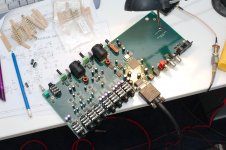
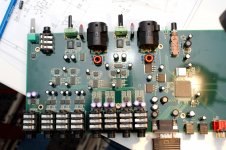
I've attached some (hopefully helpful) diagrams and photos which I'm going to refer to.
What I've found
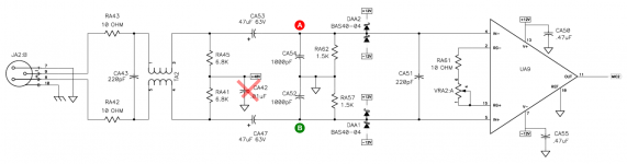
If I connect a capacitor from (A) to ground then noise goes away. I tried things like a 0.47uF 50V. The result is the speech sounds crystal clear.
The same can't be said for point (B), doing so has no audible effect.
So my novice conclusion is that CA54 (1000pF) is actually faulty and a break in the circuit -- and that noise from the ground and +/- 12V supplies enters IN- of the amplifier (UA3). How wrong am I?")
Interestingly I can replicate exactly the same results on the corresponding capacitor in the second preamp on the board.
So... I think I need to replace CA54 with some capacitor, and probably CA52 as well just for consistency? (and repeat for the second preamp)
Do I need to order an exact replacement (film or ceramic?), or is it sane to use any matched pair of capacitors? Specifically, I already have a bag of these 0.47uF 50V electrolytic capacitors handy, and not a lot else.
How I got there
I'll tell you my logic because I can easily be wrong. I'm using a phantom powered mic (Behringer B1). I started with knowledge the hiss is happening on both preamps, which means:
I noted that CA42 (on the diagram) is actually not present. But since the +48V already has lots of capacitors (including 63V 47uF connecting it to ground) I conclude that's why it was omitted.
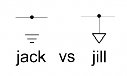
One difference is the notation. The PSU schematic uses 'jill' whereas the audio one uses 'jack' for ground. Both are from the same publication. I suspect this is an important difference; what does it mean?
Since the shared circuitry checked out, I experimented with adding a capacitor across CA50 or CA55, with no affect on the noise. And the noise still goes up and down with the trim control (VRA2:A). Conclusion: it's the audio input to the UA9 that is noisy.
I tried placing a larger capacitor (probably 0.47uF) across CA51; the noise was reduced in volume slightly, but it sounded more like I'd just low-pass filtered everything including the speech. Conclusion: CA51 is working.
I swapped out CA53 and CA47 with identical ones. No effect. Conclusion: CA53 and CA47 are working.
With it switched off, I put a multimeter between (A) and ground and once it 'settled' got 1.5K. Repeated the test with (B) with the same results. Conclusion: RA62 and RA57 are in good health.
That took me to the capacitors, When I get different effects for (A) and (B) as stated above.
Your advice appreciated!
Many thanks.
The preamps have not generally been used until recently when I noticed a problem:
- a hiss or soft white noise, about 24dB quieter than speech
- when input is really loud, it cuts abruptly out
Aided by a schematic, I think I've isolated the problem to a specific part of the circuit. I'm a little out of my depth here and would be grateful for a santity check and advice what to do next! Thanks for your time.
I've attached some (hopefully helpful) diagrams and photos which I'm going to refer to.
What I've found
If I connect a capacitor from (A) to ground then noise goes away. I tried things like a 0.47uF 50V. The result is the speech sounds crystal clear.
The same can't be said for point (B), doing so has no audible effect.
So my novice conclusion is that CA54 (1000pF) is actually faulty and a break in the circuit -- and that noise from the ground and +/- 12V supplies enters IN- of the amplifier (UA3). How wrong am I?
Interestingly I can replicate exactly the same results on the corresponding capacitor in the second preamp on the board.
So... I think I need to replace CA54 with some capacitor, and probably CA52 as well just for consistency? (and repeat for the second preamp)
Do I need to order an exact replacement (film or ceramic?), or is it sane to use any matched pair of capacitors? Specifically, I already have a bag of these 0.47uF 50V electrolytic capacitors handy, and not a lot else.
How I got there
I'll tell you my logic because I can easily be wrong. I'm using a phantom powered mic (Behringer B1). I started with knowledge the hiss is happening on both preamps, which means:
- on shared circuitry (most likely)
- both preamps failed for the same reason (less likely, but in the end seems to be the case)
I noted that CA42 (on the diagram) is actually not present. But since the +48V already has lots of capacitors (including 63V 47uF connecting it to ground) I conclude that's why it was omitted.
One difference is the notation. The PSU schematic uses 'jill' whereas the audio one uses 'jack' for ground. Both are from the same publication. I suspect this is an important difference; what does it mean?
Since the shared circuitry checked out, I experimented with adding a capacitor across CA50 or CA55, with no affect on the noise. And the noise still goes up and down with the trim control (VRA2:A). Conclusion: it's the audio input to the UA9 that is noisy.
I tried placing a larger capacitor (probably 0.47uF) across CA51; the noise was reduced in volume slightly, but it sounded more like I'd just low-pass filtered everything including the speech. Conclusion: CA51 is working.
I swapped out CA53 and CA47 with identical ones. No effect. Conclusion: CA53 and CA47 are working.
With it switched off, I put a multimeter between (A) and ground and once it 'settled' got 1.5K. Repeated the test with (B) with the same results. Conclusion: RA62 and RA57 are in good health.
That took me to the capacitors, When I get different effects for (A) and (B) as stated above.
Your advice appreciated!
Many thanks.
Attachments
Last edited:
You definitely don't want to place a 0.47uF cap from either point A or point B to ground, this will prematurely roll off the frequency response.
Your post is longer than I have time or energy to digest unfortunately, but is the noise present with nothing plugged into the microphone input? (If not it is the microphone itself that is the source of the noise.)
Your post is longer than I have time or energy to digest unfortunately, but is the noise present with nothing plugged into the microphone input? (If not it is the microphone itself that is the source of the noise.)
Should have mentioned; I use a 'known good' mic which was tested on another mixer.is the noise present with nothing plugged into the microphone input? (If not it is the microphone itself that is the source of the noise.)
Sounds like a duff CA53 or bad solder joint somewhere on the way from XLR -in to point A. Since you swapped out CA53 already, time to measure some trace resistances along the way. I'd also check RA41/45 - an unbalance there could make P48V noise audible.
"Jack" is chassis ground, "Jill" is audio circuit ground. They will generally be joined somewhere in the power supply area but kept separately otherwise.
That brings me to the "minor niggles" department. XLR pin 1 is shown to connect to circuit ground, whereas AES48-2005 mandates that it be connected to chassis ground, as shown for the shell here. (This is done to prevent ground loop currents from flowing over audio circuit ground to the power supply and become audible that way.) Mind you, I have no idea how the routing of both would differ here since there seems to be no metal chassis to connect to, plus this is not as critical on a mic input by far (a mic is floating, so no ground loops).
I would also prefer the CA52/54, RA57/62 junction not to connect directly to ground; doing so via ~10 kOhms in parallel with ~100 pF instead would give noticeably better practical CMRR as common-mode input impedance would increase a fair bit. (Stock, common-mode input impedance at low freqs is about 3k4 || 750R, so about 615 ohms - not exactly high, so very little imbalance would degrade CMRR to pedestrian values way below the chip's impressive specs, and common-mode rejection tends to be kinda important in a microphone preamp. As described, this would increase to 3k4 || (750R + 10k) or about 2.58 kOhms. That's up to 12 dB better - or less bad - practical common-mode rejection.)
In this case I don't think connecting pin 1 to chassis ground is necessarily the right thing to do as phantom power is present and needs to be returned to circuit ground not chassis ground. I might use a choke to circuit ground and a cap to chassis to deal with phantom power return currents and EMI, but it's been a while since I did a mixer/MI design.
All moot in this design in any event.
Again with phantom power the usual industry convention is equivalent to 3.3K in series with the 48V phantom power, most mics, not all would probably be fine with 10K//10K as opposed to 6.8K, but again standard practice.
To the OP, are you sure this wasn't always noisy? Both channels doing the same thing or one channel only? Unfortunately not all mic amps are cut from the same cloth.
Are nodes A and B both close to 0 V when the amplifier is switched on?
It is weird that putting an extra capacitor on node A has a different influence than putting an extra capacitor on node B, this shows that there is some asymmetry somewhere. When you swap CA52 and CA54, does adding 0.47 uF to node A still do more than adding 0.47 uF to node B or is it reversed?
It is weird that putting an extra capacitor on node A has a different influence than putting an extra capacitor on node B, this shows that there is some asymmetry somewhere. When you swap CA52 and CA54, does adding 0.47 uF to node A still do more than adding 0.47 uF to node B or is it reversed?
Your noise is almost certainly due to leaky Schottky diodes DAA1 & 2.
THAT used this in their early Datasheets but changed to cheapo 1n4004s. Glass Passivated 1n4004GP s if you can get them.
Use this even if your Preamp chip is TI or AD
It affects many, otherwise very good preamps, eg the MOTUs.
Don't replace with Schottkys as the problem WILL come back.
THAT used this in their early Datasheets but changed to cheapo 1n4004s. Glass Passivated 1n4004GP s if you can get them.
Use this even if your Preamp chip is TI or AD
It affects many, otherwise very good preamps, eg the MOTUs.
Don't replace with Schottkys as the problem WILL come back.
Hi everyone, many thanks for your help and suggestions, many of them! Comments below.
Valid question, as both channels have the same hiss. But both have definitely performed much better in the past -- there was a day when we noticed the hiss had appeared. I've been using the same mic all along. It's a reputable piece of hardware, yet on this one the hiss is loud and you're almost talking 'through' it.
Thanks sgrossklass. I'll see what I can test. I'll prioritise looking for a faulty component -- bad solder joint seems unlikely to happen in the same way on both preamps.
(And thanks for the upgrade tips! If the repair involves me replicating some of the circuit on a board then I'll have this in mind)
Tested just now with a digital multimeter against ground on pin 10 of the UA9 chip, and they are all 0.00V.
Yup, and that's still the most striking thing for me too. Two preamps, both hissing, and both with the same asymmetry when poked.
I haven't tried this, but I am limited in how often I can do these swaps, as the solder points on the board are fragile; I already nearly damaged one of the others by changing it only once.
I've ordered some replacements so one of my options will soon be I could replace CA52/54 for brand new ones.
Thanks kgrlee. Do you think this would cause the asymmetry? These are small surface mounts and would be tricky to replace.
The odd thing I can't get my head around is the asymmetry, combined with both preamps showing the fault.
I've ordered some spares; replacements for CA53/47 and a mixed pack of smaller ceramic ones. I think my next test is going to be to repeat the previous poking but with a 1000pF capacitor (as in the spec) rather than the much larger one.
It's not impossible I could replicate most of the circuit on a piece of breadboard if I thought it would fix it. I could connect in at CA54/RA55 and its counterparts on the hot side. But then a trusted colleague at work has his money on faulty the chip UA9
Thanks everyone for taking the time to read and comment, I'll let you know when I do some of these tests!
To the OP, are you sure this wasn't always noisy? Both channels doing the same thing or one channel only? Unfortunately not all mic amps are cut from the same cloth.
Valid question, as both channels have the same hiss. But both have definitely performed much better in the past -- there was a day when we noticed the hiss had appeared. I've been using the same mic all along. It's a reputable piece of hardware, yet on this one the hiss is loud and you're almost talking 'through' it.
Sounds like a duff CA53 or bad solder joint somewhere on the way from XLR -in to point A
Thanks sgrossklass. I'll see what I can test. I'll prioritise looking for a faulty component -- bad solder joint seems unlikely to happen in the same way on both preamps.
(And thanks for the upgrade tips! If the repair involves me replicating some of the circuit on a board then I'll have this in mind)
Are nodes A and B both close to 0 V when the amplifier is switched on?
Tested just now with a digital multimeter against ground on pin 10 of the UA9 chip, and they are all 0.00V.
It is weird that putting an extra capacitor on node A has a different influence than putting an extra capacitor on node B, this shows that there is some asymmetry somewhere.
Yup, and that's still the most striking thing for me too. Two preamps, both hissing, and both with the same asymmetry when poked.
When you swap CA52 and CA54, does adding 0.47 uF to node A still do more than adding 0.47 uF to node B or is it reversed?
I haven't tried this, but I am limited in how often I can do these swaps, as the solder points on the board are fragile; I already nearly damaged one of the others by changing it only once.
I've ordered some replacements so one of my options will soon be I could replace CA52/54 for brand new ones.
Your noise is almost certainly due to leaky Schottky diodes DAA1 & 2.
Thanks kgrlee. Do you think this would cause the asymmetry? These are small surface mounts and would be tricky to replace.
The odd thing I can't get my head around is the asymmetry, combined with both preamps showing the fault.
I've ordered some spares; replacements for CA53/47 and a mixed pack of smaller ceramic ones. I think my next test is going to be to repeat the previous poking but with a 1000pF capacitor (as in the spec) rather than the much larger one.
It's not impossible I could replicate most of the circuit on a piece of breadboard if I thought it would fix it. I could connect in at CA54/RA55 and its counterparts on the hot side. But then a trusted colleague at work has his money on faulty the chip UA9
Thanks everyone for taking the time to read and comment, I'll let you know when I do some of these tests!
Ok, I'm back. With good news -- the preamps are fixed. Everything is crystal clear 
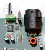
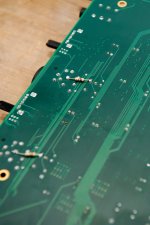
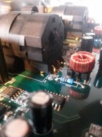
The short story: a faulty RA43 breaking the circuit, with the exact same fault in the other preamp; see pic for the fix.
The full story
You remember I had a cheat where the noise seemed to disappear if I put an capacitor between point A and ground. I repeated that with a 1000pF capacitor (instead of 0.47uF), effectively replacing the one in the schematic that I thought might be faulty -- but it had no effect.
Then I tried just a piece of wire; shorting A (effectively IN-) to ground, and got the same effect; the noise almost all disappeared. I noticed the speech seemed to be exactly the same volume. I shorted B to ground, and the speech disappeared but the noise stayed the same; looks like IN- is carrying noise, and that IN+ was the signal, and so UA9 outputs a nice little mix of the two.
So started tracing the few points between XLR and point A that I had not yet tested (sgrossklass suggested this) and found a break at surface mount resistor RA43.
I tested a resistor in place of the break and all the noise disappeared. A working preamp. I suppose the entire IN- side was acting as an antenna to pick up noise.
But this leaves one final puzzle: since it's not a common piece of circuitry then how could both pre-amps break in exactly the same way? The source of much confusion
Take a look at the attached picture of the faulty surface mount resistor, RA43. It's placed slightly under the XLR socket, and it's the only component in this position; RA42 is not touching the XLR socket. The other preamp on the board is exactly the same physical layout. Could a physical fault result from plugging and unplugging the XLR, causing the surface mount joint to fail? Perhaps I am on to something, I thought!
So I made my fix permanent (see picture) and then to eliminate a possible return from the dead, carefully removed the surface mounts.
But the puzzle remains! Because the removed RA43 is not functioning; there's no continuity across it. So it seems that RA43 has failed, and the exact same has happened in the other preamp. And RA42 is not affected. Answers on a postcard?
Many thanks for all the help. I've learned a lot here, and I hope you find the conclusion equally as interesting!
Attachments
Could a physical fault result from plugging and unplugging the XLR, causing the surface mount joint to fail? Perhaps I am on to something, I thought!
Yes, its very common for pcb mounted connectors to fail mechanically, its best to have connectors fixed securely to a metal chassis mechanically. Here the stress from the connector has flexed the pcb nearby and cracked the resistor. In hindsight the resistor should have been sited futher away. Some people break connectors and pcbs more efficiently than others!
Last edited:
Hello Mk1.Ok, I'm back. With good news -- the preamps are fixed. Everything is crystal clear
The short story: a faulty RA43 breaking the circuit, with the exact same fault in the other preamp; see pic for the fix.
The full story
You remember I had a cheat where the noise seemed to disappear if I put an capacitor between point A and ground. I repeated that with a 1000pF capacitor (instead of 0.47uF), effectively replacing the one in the schematic that I thought might be faulty -- but it had no effect.
Then I tried just a piece of wire; shorting A (effectively IN-) to ground, and got the same effect; the noise almost all disappeared. I noticed the speech seemed to be exactly the same volume. I shorted B to ground, and the speech disappeared but the noise stayed the same; looks like IN- is carrying noise, and that IN+ was the signal, and so UA9 outputs a nice little mix of the two.
So started tracing the few points between XLR and point A that I had not yet tested (sgrossklass suggested this) and found a break at surface mount resistor RA43.
I tested a resistor in place of the break and all the noise disappeared. A working preamp. I suppose the entire IN- side was acting as an antenna to pick up noise.
But this leaves one final puzzle: since it's not a common piece of circuitry then how could both pre-amps break in exactly the same way? The source of much confusion
Take a look at the attached picture of the faulty surface mount resistor, RA43. It's placed slightly under the XLR socket, and it's the only component in this position; RA42 is not touching the XLR socket. The other preamp on the board is exactly the same physical layout. Could a physical fault result from plugging and unplugging the XLR, causing the surface mount joint to fail? Perhaps I am on to something, I thought!
So I made my fix permanent (see picture) and then to eliminate a possible return from the dead, carefully removed the surface mounts.
But the puzzle remains! Because the removed RA43 is not functioning; there's no continuity across it. So it seems that RA43 has failed, and the exact same has happened in the other preamp. And RA42 is not affected. Answers on a postcard?
Many thanks for all the help. I've learned a lot here, and I hope you find the conclusion equally as interesting!
I need your help please.
I see your blog content and i search until i found this post.
A friend has given me a layla 3g that I was thinking of throwing away.
But I have a problem, it doesn't find the PCI card and I think that without it I can't do anything.
You, who are an engineer, could you tell me if I can make it work without the card? Or by chance the midi interface has died and you keep the card?.
Thank you
- Home
- Live Sound
- Instruments and Amps
- Repairing a hissing microphone preamplifier