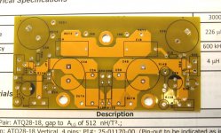
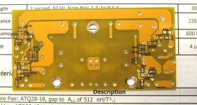
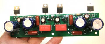
Attached are pictures of a PCB I ginned up over last weekend for an open loop headphone amp using a mosfet with feedback to simulate triode characteristics.
Use of a solid state "triode" allows one to bump up the bias current and avoid use of an output transformer. I could do the same thing using a real vacuum state triode, but then would be stuck with an expensive and heavy output transformer, or, for a parafeed solution, an expensive transformer plus a tubby coupling cap. The goal here was a headphone amp with good listening characteristics with less-than-stellar THD, just like your classic triode open loop SE setup. Simulation shows dominant 2nd harmonic with decreasing high order products. I decided to pump up the bias current to reduce the THD, up beyond what I would actually need for power delivery into a headphone load of 30-50 ohms. If I were using an actual triode, most likely the power for the filament(s) would exceed the power dissipated in the whole amplifier.
For this board run, I decided to use yellow solder mask for a different look, along with black silk screen. The actual results surprised me, as the yellow solder mask turns out to be a lot more transparent and subliminal than expected, allowing me to see the traces clearly. The black silk screen has excellent readability.
For this first approach, I decided to backtrack to an earlier triode emulation circuit using a jfet and a mosfet. I may also entertain the possibility of using a later implementation using a p-channnel and n-channel mosfet, as it allows me to use a pot at the input to control volume. I could use a pot with this design, but the resistance value would be inconveniently low.
Attachments
Last edited:
OK, here's the basic circuit with all placeholder components. Vlues will change as I optimize simulations. It's a simple circuit - imagine a triode with curent source load, translated to a SS circuit with lower "plate" resistance to directly drive headphones via a coupling capacitor.
Attachments
I have some AC alarm-type wall transformers to generate the main supply. I'll be using a cap multiplier to smooth out the main supply and add a slow-rise feature to eliminate turn-on thump. I'll use a voltage multiplier scheme to generate the minus supply, sizing the capacitors to limit current, and perhaps using a pair of GaP green LEDs in series for bias regulation.
Here's another variant I like to call the "buffered fake SIT", with high input impedance allowing insertion of a suitable impedance volume control at the input. THD is a little higher, but still mostly 2nd harmonic.
Attachments
Here's a variant of the first instance of the headphone amp. The polarity of the Schade buffer has been turned around to allow use of readily available N-channel jfets, and a input buffer has been added so that I can use a 50-100k volume pot and still be able to drive the somewhat low 22k input impedance without overloading the input source. R19 is the resistor that will be replaced with a 50k pot and a 499k resistor from wiper to ground so that input grounding does not go away if the pot wiper happens to lift. R19 in practice will be a 100k resistor plus a 50k pot in series to allow adjustment of output centering and hopefully eliminate the need to select jfets and the IRF510 output mosfet. I'm currently trying to squeeze all the added stuff into a new, slightly larger board size. This will still be 2 channels worth of amp on a very small board. Gain with the current setup is ~8.5X, and distortion is relatively low and overwhelmingly 2nd harmonic.
Attachments
")
Here's the amplifier response with square wave excitation - gain is ~8X, just like in the sim. There was a little overshoot on the output waveform, cured with a ~0.5pF "gimmick" type capacitor across R16. Rise and fall times are very respectably fast, and much better than I expected. Right now, I'm dumping the output of a 50 ohm impedance signal generator directly into the input buffer, so things are quite zippy with the low impedance drive. With a 50k volume control at the input as planned, rise and fall times will be more sedate, but I'm not crying...
Ed - for clarification, the green is the input waveform, and the blue is the output.
Ed - for clarification, the green is the input waveform, and the blue is the output.
Attachments

Last edited:
It uses a 16.5 VAC plug-in AC wall transformer used often to power alarm panels.
I've recently taken to using those AC wall-warts too - easy to source and great value for money.
- Status
- This old topic is closed. If you want to reopen this topic, contact a moderator using the "Report Post" button.
- Home
- Amplifiers
- Headphone Systems
- Simulated Triode (Schade) SE OL Headphone Amp