What failed in particular?
Part of the board is a different color and the fuse put smoke out. I have no idea how to go about seeing what failed as no resistors burned or capacitors blew out.
When building a PSU from scratch like that, it is best to take baby steps.
Populate the rectifier - verify that voltage and polarity make sense.
Populate the filter capacitor - check that voltage is being smoothed properly and is about where you'd expect (~30 V for a 12V + 12 V).
Only then proceed with the regulator.
As the fuse went down so violently, I can only assume something like an accidental short in the rectifier or miswired rectifier diodes so it puts out a negative voltage, which the filter capacitor isn't happy with.
When building a PSU from scratch like that, it is best to take baby steps.
Populate the rectifier - verify that voltage and polarity make sense.
Populate the filter capacitor - check that voltage is being smoothed properly and is about where you'd expect (~30 V for a 12V + 12 V).
Only then proceed with the regulator.
As the fuse went down so violently, I can only assume something like an accidental short in the rectifier or miswired rectifier diodes so it puts out a negative voltage, which the filter capacitor isn't happy with.
I managed to rebuild it and everything sounded good, but I found that I have a 60 Hz or 120 Hz hum. When I put the amplifier on battery it dissappears. I need to do a better layout on the PSU and report back.
I finally built my power supply for this amplifier and immediately blew the fuse. Is there anything obviously wrong with my as built PSU from what you can tell?
View attachment 834752
View attachment 834755
View attachment 834753
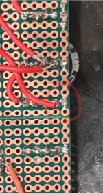
Just revisiting your previous photos of the board that let the smoke out.
Can't help but wonder if you had a short at the circled area:
Hard to tell by photos sometimes.
Attachments
Just revisiting your previous photos of the board that let the smoke out.
Can't help but wonder if you had a short at the circled area:
Hard to tell by photos sometimes.
Based on some more reading, do you think this will be a better design with regards to ripple, PSRR, etc.? I want to have a better design, layout etc. before I try to rebuild the PSU.

Attachments
When building a PSU from scratch like that, it is best to take baby steps.
Populate the rectifier - verify that voltage and polarity make sense.
Populate the filter capacitor - check that voltage is being smoothed properly and is about where you'd expect (~30 V for a 12V + 12 V).
Only then proceed with the regulator.
As the fuse went down so violently, I can only assume something like an accidental short in the rectifier or miswired rectifier diodes so it puts out a negative voltage, which the filter capacitor isn't happy with.
Everything looked okay, but it appeared to be an issue with the diodes as well as some poor soldering. What do you think of this as a new PSU?

What failed in particular?
The diode cracked straight in half. I will be using 1N4007's from now on. Have a look at the new design?
If you're concerned about PSRR then put the current source (I'd use a discrete one for lower capacitance) to the +ve rail and swap the FET for a P-channel one. Then the whole circuit draws a constant current, irrespective of signal.
What about the PSU now?
Attachments
- Status
- This old topic is closed. If you want to reopen this topic, contact a moderator using the "Report Post" button.
- Home
- Amplifiers
- Headphone Systems
- IRF610 Class A Headphone Amp