What devices are you using ?
If you want to use BJTs, you should use ones with high hfe.
E.g. BC550C, BC560C.
200 is rather low to me.
And ideally, for best results you need 2 quads NPN & 2 quads PNP.
Within 5% or better of each type, and 10% or better between N & P.
I buy 100 of each type for matching.
The devices can always be use for other projects.
But the circuit will work also without matching, especially when you use negative feedback.
Patrick
Hi Patrick,
These are ZTX851 and ZTX951.
I would not bet that these hFEs precise in the absolute sense. Every DMM I have shows different values. Actually two are pretty close one is a bit off. What I made sure of is that I compare values coming from the same multimeter.
Since you asked about the devices I will take the liberty of asking whether I could get away with less powerful ztx something like ztx450/550? ZTX851/951 strike me as very powerful in this application. I still would prefer to go for e-line packages as they fit better on the boards.
I would prefer not to use NFB.
Last edited:
BC327-40/BC337-40 sorted.
I started with 30 of each. Got a few decent quads but N too far from P. I figured out that it was N which was way too far from the mean so I got 100 more of Ns. These N's were pretty boring to measure. All close to the same value with a few outliers.
The added value of this project for me is that I read a lot about current mirrors and why 3/4 transistor version is better than a simple mirror.
I guess it is EUVL's way of doing things: you need a current mirror: ah! there you go: you need a matched quad.
I am very slow but it is shaping up.
I read that the version with FET current mirrors should be run with +-24V.
Given that I am using BJT mirrors shall I lower the voltages by say 3V?
In principle everything should be within acceptable conditions with BJTs but I better ask.
I read that the version with FET current mirrors should be run with +-24V.
Given that I am using BJT mirrors shall I lower the voltages by say 3V?
In principle everything should be within acceptable conditions with BJTs but I better ask.
Attachments
I trimmed the front end of one amp today. I followed the procedure described in the doc.
I got -1..-2mV (accross R11) which seems to be reasonable to me.
The only worrying thing is that it takes about 20sec to get below 20mv.
I am using a cap multiplier as the power supply(*).
I was planning to build a delay circuit which shorts the output for the first few second when turning on. So I guess I will need to make it at least 20sec.
What is normal time people have to wait to observe reasonable offset (in my other headphone amps I want to see less than 10mV; in this case I can tolerate 20mV if I know it is going down quickly).
(*) I do not have a lab PS with current limiting. I used resistors in series with the circuit to see whether everything is all right. As long as nothing goes wrong I finally remove the resistors.
Last edited:
Yesterday I trimmed the front end of the other channel.
Today I installed the output laterals.
I spent loooong hours trimming the output stage. I am happy with final result: both channels within +/-10mV.
People building this amp here are way more knowledgeable then I am.
So below part is for the benefit of those who are more challenged by this design.
I will repeat something which Partick has mentioned here many times: make sure you understand the circuit and what you are doing.
I thought I did my homework, but not well enough it seems. I was confused about the values of IV converter R21 and R22 in the BOM (124 and 75Ohm). Or to precise I was not brave enough to question these values as initial values for trimming, I was more willing to question my own Vgs measurements.
Well the doc says CLEARLY how to calculate those given Vgs and Ijfet. I could not justify the values in the BOM (and I use different FETs) but still went ahead to try it on a live amp!
After fiddling around I understood, that this is never going to work and went back to my calculations! The result is above. The problem was that I had to trim my own output stage, with my own FETs not Patrick's even if he is a guru.
This is not to criticise Patrick's great design, nor the doc. The doc is in fact excellent! The problem is in the chair, as usual.
Attachments
It is not a design issue.
It is that you misunderstood what the document said, and how the circuit works.
The values given (124R & 75R) were typical values, or values that applied to my build using my FETs.
It gives you an idea of the order of magnitude. Nothing more.
There is no way I can give a value which covers all possible combination of Idss and Vgs.
But I have already demonstrated how to calculate your starting values.
And the final values you always have to trim, as in many other builds after my own.
There are circuits that enables automatic setting of bias currents.
But they tend to mess with the music, so I personally do not like using them.
Example is the famous optocoupler bias of Pass's WHAMMY.
Anyway, you have now got the right result.
Which is what matters.
Cheers,
Patrick
Hello!
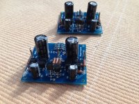
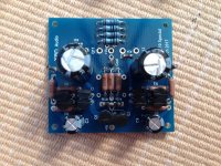
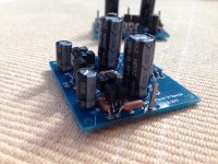
After a long break (have been busy with some other small projects and pursuing other hobbies) I have put up a mock up version of the amp. I will post the pics tomorrow, though I know Patrick will not approve my long cables/antennas even in a mock up version.
I am using capacitance multipliers for PS and a x-over circuit.
I have spent 1-1.5 hours today listening to this amp going from my throw away headphones through more expensive. Ended up with HD600.
This amp is seriously good! In fact the best I have now but I kind of expected this.
The other two are Pelerano's Zen HP and Whammy with Burson.
The only question I have is: is there any special grounding scheme to follow?
Using one PS for both channels the absolutely quiet. But I get hum with two PSs (fed from one transformer). I will have to sort this out as my single PS is getting too warm, not hot, but still.
I created a ground point connecting input RCA grounds where I soldered the amps grounds, output jack ground. The PS ground goes to the ground on amp pcbs.
Glad you are successful and like the results.
>The only question I have is: is there any special grounding scheme to follow?
I can only tell you what I have / use myself.
The inputs have to share a common ground, as this is required by the cross feed circuit.
From then on, everything is dual mono.
That means 2 completely separate +/- power supplies, separate Gnd wirings to pot and then to amp, separate output GNDs.
I use exclusively 4 wire cables and connectors, as in a balanced headphone amp.
For serious amps, I use LEMO 2B 4-pin. For others 3.5mm TRRS.
TRRS is wired as +Left, +Right, Gnd Left, Gnd Right.
That even applies to the SHPP protection circuit, even though the latter is powered by one of the power supplies.
The power supplies can be from one transformer.
But the ones I use have 4 separate secondaries.
Hence they are electrically separated from each other.
The DAO SE all-FET Class-A ZGF Headphone Amplifier
The dual mono construction ensures you have as good left/right separation as possible.
And of course even better would be separate transformers.
The Pioneer Super Linear Circuit
XEN ZGF Portable Headphone Amplifier
Patrick
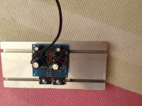
Getting rid of the hum with two power supplies turned out to be easier than I suspected.
I was lazy in my mock up setup: I had already 3 cables (+/gnd/-) soldered to both amp boards. I soldered them directly to +/gnd/- of both power supplies.
Today I disconnected gnd PSs connections and ran them to the star gnd point at the input.
Pretty elementary...
I did not expect that I can get away with this so easily. Especially that I use 3 pole phone jack. I will need to investigate at least the 3.5mm TRRS you suggested.
I was asked about FET sourcing.
For the input JFETs, you can always buy from the DIYA store.
In this particular application, it is also beneficial to use the V grade.
And I have bought those from Alweit before.
Toshiba Original 2sj74v/2sk170v matched pair (0.05 MA) | eBay
For the MOSFETs, best to buy a bunch from Mouser and match yourself.
If you are not chasing perfection, then use BJTs and just measure hfe with multimeter.
UTHAiM -- Just for Fun
There are also matched 2SK1058/2SJ162 on offer from a Hong Kong Ebay dealer.
Looks creditable, but I have not bought from him before.
Cheers,
Patrick
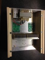
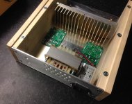
The chassis is taking shape.
I wish I had the skills and tools to produce what some other people are showing here.
Anyway this my poor mans humble rendition. Very similar to my Whammy. The only difference is that the front panel will be made out of wood not aluminium.
Initially I did not plan to use the socket with a RF filter, so now I ended up with PS boards very close to the high voltage terminals. I do not like it. I will have to see what can be done about it.
I need to check the required distance between 240V terminals and other circuity. Maybe a small division wall will suffice. Edit: Checked the requirements re mains voltage. I am fine, it will be just awkward to disconnect the cables from the filter...
As you can see there are many metal outer parts. They all be connected to the filter earth.
Attachments
Last edited:
- Home
- Amplifiers
- Headphone Systems
- UTHAiM -- Just for Fun