I actually thought about that, I have a few 3886's, but using a more linear op amp for the volage gain and a class A output stage appealed to my DIY sense more. Next step willprobably be the full class A design I posted initially and a some stage a valve design. At some point I'll try the MOSFET buffer for comparison.
Hi
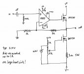
Opamps I have lived with and recommend, every one of these needs a good pass transistor
power supply of 16v and don't forget to decouple the base of TO92's with at least 220nf
and 100n across emitters.
AD825 very good all round performance - very good low frequency reproduction
OPA 627 excellent
OPA1611 excellent
Cheers / Chris
.
Forgot to mention this earlier, but the output device is thermally compensated by the feedback loop through the opamp. As you said, the opamp outputs will sit at the "on" voltage for the output device to maintain 0v on the output with the appropriate Iq as set by the CCS. For bipolars, if Vbe decreases due to increased device temperature, it will attempt to pass more current (through the load, not the CCS) and Vout will increase, which will be fed back to the opamp's -ve input. The opamp's output DC voltage will then decrease thereby applying thermal compensation.
I think that's the case anyway, feel free to dispute that.
In my case I've used a way undersized heatsink and although it gets very hot (I'd estimate 60-70degC), there seems to be no thermal stability problems as the DC output of the opamps decreases.
Also definitely post your old schematics if you can find them, I'd like to see some other interpretations of this type of amp!
A large heat sink is essential because there's no temperature compensation and below a certain current MOSFETS are positive just like a BJT (depending on type).
Forgot to mention this earlier, but the output device is thermally compensated by the feedback loop through the opamp. As you said, the opamp outputs will sit at the "on" voltage for the output device to maintain 0v on the output with the appropriate Iq as set by the CCS. For bipolars, if Vbe decreases due to increased device temperature, it will attempt to pass more current (through the load, not the CCS) and Vout will increase, which will be fed back to the opamp's -ve input. The opamp's output DC voltage will then decrease thereby applying thermal compensation.
I think that's the case anyway, feel free to dispute that.
In my case I've used a way undersized heatsink and although it gets very hot (I'd estimate 60-70degC), there seems to be no thermal stability problems as the DC output of the opamps decreases.
Also definitely post your old schematics if you can find them, I'd like to see some other interpretations of this type of amp!
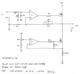
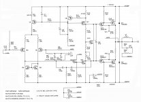
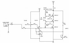
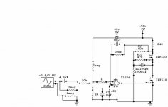
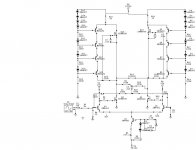
OK, I've gone through the moldy archives. Here are 3 circuits. The simple one is the one I built and listened to and was very impressed. Unfortunately I think I gave it away (like most projects) as I can't find it. The one with the opamp driven current sink I built and measured, but never did a board and chassis. I can't remember if it had any advantages or disadvantages, but the current was certainly more precise. The final circuit I've had to redact some of the schematic as I designed it for a commercial purpose, but its a blameless design of really superb performance. I did the board to allow experimenting with grounds, thus the notations of HCG and LCG for high current and low current ground paths. You'd want to change the input network. Or not- it might work fine as is. Don't wrap the output inductor around anything (people usually use the resistor) as that increases distortion. There are also two non-obvious transistors that should be in thermal contact (see D. Self book) and I lay them out next to each other flat to flat, grease 'em up and put a Ty-wrap around them.
Attachments
Last edited:
Silly me- I didn't even notice until now that those first two circuits are more different than I thought. One uses an N-ch fet and the other uses a P-ch. Note the input polarity on the opamps because of that.
FWIW, one can also go single supply, put the current source on top, bias the circuit half way up and AC couple both the input and output. That gives, I believe, a completely indestructible amplifier for any load condition.
FWIW, one can also go single supply, put the current source on top, bias the circuit half way up and AC couple both the input and output. That gives, I believe, a completely indestructible amplifier for any load condition.
Here is something all-discrete, class A, high performance and delightfully outlandish:
The tringlinator: http://www.diyaudio.com/forums/headphones/165131-tringlinator-mos-based-tringlotron-amplifier.html
A chip version also exists: the chtringlunator:
http://www.diyaudio.com/forums/chip...oss-tringlotron-regulator-chip-amplifier.html
The tringlinator: http://www.diyaudio.com/forums/headphones/165131-tringlinator-mos-based-tringlotron-amplifier.html
A chip version also exists: the chtringlunator:
http://www.diyaudio.com/forums/chip...oss-tringlotron-regulator-chip-amplifier.html
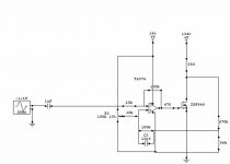
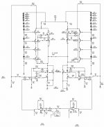
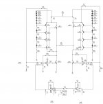
Here are just a few diiferent versions the first two I built and the rest have been simulated without errors.
I plan on trying these out.
the 1000v version I have also using opamps instead of transistors as I forget that I did both of that version.
I originaly design these circuits to power my esl's and esphones.
jer
I plan on trying these out.
the 1000v version I have also using opamps instead of transistors as I forget that I did both of that version.
I originaly design these circuits to power my esl's and esphones.
jer
Attachments
Last edited:
A/DSL op amps can handle enough current to make great headphone drivers
wrap a good fet input op amp around it in a multiloop and you can't mach the performance in discretes
the TPA6120/THS6012 is my favorite for driving dymanic headphones
it can even be Class A biased AD8397-class A? show push-pull Class A output bais for op amps
wrap a good fet input op amp around it in a multiloop and you can't mach the performance in discretes
the TPA6120/THS6012 is my favorite for driving dymanic headphones
it can even be Class A biased AD8397-class A? show push-pull Class A output bais for op amps
One thing I would like to piont out Is that even though these circuits employ opamps is that they are still operating in class a mode.
Because when the opamp is powerd with a high enough voltage it is drivng the fets entirely in its linear range and never hits the crossover point.
If it does it would be at extermly high peaks and at the risk of destruction of the fets.
Now my transistor driven design would be considered pure class a though.
jer
I started designing these type of circuits around 1995 and the stacked version in 2003 but I did not actualy build one until 2007.
I have also used them in a BTL configuration and used a little pizeo driver as a load and I was amazed in how clean and loud it was just hanging off of the breadboard.
I thought the thing was going to shatter.
I first tried sine waves ofcourse and then used some music.
I was using a resistor load and they weren't a high enough wattage and burned up quite a few to the point that I didn't have enough parts to continue.
It wasn't until a couple of months ago I figured out how to employ a high ampreage CCS to replace the load resistor.
So,I have yet to build that vesion as it is one of the many projects that I have going all at once!
the cool thing was I tried every different type of fets that I had rangeing from IRFZXX, IRF510,IRF640,IRF740 and IRF840 and they all worked.
jer
Last edited:
Ha! Gottcha all beat in the old fart department. I just found my original drawing. It's basically the same as I posted, but with different gain. It's dated 1985, so that was 26 years ago!
Jer, thanks for those circuits- interesting thoughts for some projects I'm looking at right now.
Jer, thanks for those circuits- interesting thoughts for some projects I'm looking at right now.
- Status
- This old topic is closed. If you want to reopen this topic, contact a moderator using the "Report Post" button.
- Home
- Amplifiers
- Headphone Systems
- All Discrete Class-A Headphone Amp