@jpk73, sorry but the boards sold out some time ago.
The footprints are saved in the board file. So you don't need them unless you're trying to use them for something else.
If you want to scavenge some of them you can hit Ctrl-E (Cmd-E on Mac) to edit the footprint, and the do a Save As... to store it in one of your libraries.
Cheers,
Jeff.
The footprints are saved in the board file. So you don't need them unless you're trying to use them for something else.
If you want to scavenge some of them you can hit Ctrl-E (Cmd-E on Mac) to edit the footprint, and the do a Save As... to store it in one of your libraries.
Cheers,
Jeff.
The footprints are saved in the board file. So you don't need them unless you're trying to use them for something else.
Thanks! I didn't want to use them for something else, it just wasn't possible to sync the pcbs to the schematics. I fixed that and re-packed them as stand alone projects compatible with kicad 5.1.6., see attached zip file.
Attachments

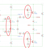
Both differences are due to the quasi-complementary design. A complementary design (in contrast) is usually completely symmetrical.
(You'll also note that on the amplifier boards the compensation networks for the upper and lower drivers have different values. Some cloners -- such as Avondale -- don't buy that and keep the compensation networks symmetrical. I haven't listened to both so I can't comment, but as this is a nostalgia project I went with Julian's design.)
(You'll also note that on the amplifier boards the compensation networks for the upper and lower drivers have different values. Some cloners -- such as Avondale -- don't buy that and keep the compensation networks symmetrical. I haven't listened to both so I can't comment, but as this is a nostalgia project I went with Julian's design.)
It comes down to the inescapable fact is that npn and pnp are electrically different due to the asymmetrical nature of electricity. “Complementary” transistors aren’t...or aren’t enough for audio. Transformers are: e.g. a push-pull tube circuit with matched tubes is pretty symmetrical. The right question is not “Why aren’t the filters the same?” but is “How different should the filters be?” 😎
Indeed; there's also a raging argument on Lateral FETs regarding whether or not to compensate for the fact that the p-channel device has a lot more input capacitance. Some advocate adding an external gate-to-source capacitor to the n-channel device; others unbalance the gate-stoppers to yield the same RC-time-constant, and yet others say to do nothing as the other differences will swamp out the input capacitance difference anyway.
You picks your poison...
You picks your poison...

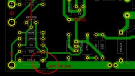
Jeff, I am preparing your files for my needs and have made some small changes to the PCB in order to squeeze in connectors, also I switched on component values in silk, see attached screen shot.
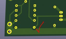
DRC occasionally complained about TR4 / TR6, so I tried to adjust them a bit to get rid of the DRC-messages and finally turned TR6 by 180 degrees (after that I realised that the footprint outlines were not fully closed). Here are my questions:
1.) would the small layout changes near the out connectors and the 180° turn of TR6 restrain amp performance in any way?
2.) how thick should I order the PCBs copper layers to be?
3.) the amp board looks like as if it was intended to be powered from 4 supplies (2 negative + 2 positive): which combination of regulator boards and inverted regulator boards would be the best solution?
Attachments
Last edited:
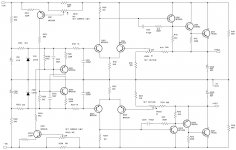
To do the other test connect your leads across the capacitor in front of the VBE spreader (TR5).
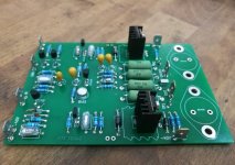
Jeff, thanks for this great project! As you know I did some small mods to your boards but kept your name on them if you don't mind (see attached picture).
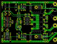
I populated my first PCB today: it's a 2oz board from JLCPCB. Parts according to your BOM except for the ZTX108 (I used a 2N5551), and for the 10uF input cap I used a Kemet 35V. I mounted normal TO220 heat sinks for now: where can I find the original heat sinks? The output transistors will be the MJs but I didn't fit them yet.
I matched BC239Cs (not the ones from Langrex) with the small device tester you recommended here and found 2 pairs with identical hfe and vbe readings and fitted one of these pairs to the board.
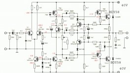
I plan to go with the inverted reg boards, but for now I hooked up a 32-0-32V DC power supply. I measured 2.2V across C7 (the capacitor in front of the VBE spreader). All small voltages are close to the values shown on atteched schematic.
What else can I check prior to fitting the output transistors?
Attachments
Last edited:
Has your negative rail sagged a bit?
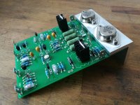
Both rails are at +/-32V, I don't have a PSU with more for now. The MJs are fitted, I have ceramic pads with thermal paste between them and the heat sink, and none of the contacts short to the heat sink.
Just to make sure: I shall power it up with nothing connected to the output, and the input has to be shorted to ground when I adjust bias and check voltages and DC offset?
Attachments
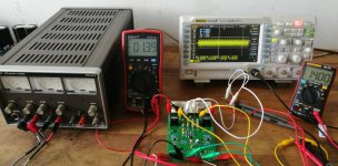
Ok, did as you said and fired it up! The board doesn't draw much current, the analog meters of the PSU are almost at zero.
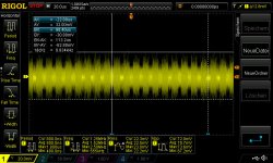
When disconnecting the speaker cable after some minutes the scope shows some square looking oscillating around 88kHz, Vpp including noise is about 70mV.
The left multimeter shows a small negative DC offset at the output of -1.4mV.
The right multimeter is connected to TP1-TP2: it was not easy to set the pot to 14mV as it isn't multiturn, also the voltage climbs over time and the output transistors get hand warm after some time. I hope all that is normal!
Should I adjust bias to 14mV after warm up or when cold?
Attachments
Last edited:
14mV when warm (in a box or something to keep the heat in). It's not very critical though as the optimal bias for the emitter-follower pair (top) is different from the sziklai pair (bottom) -- so 14mV is a compromise to start with.
-1.4mV offset is tiny. Anything under +/- 50mV is fine.
-1.4mV offset is tiny. Anything under +/- 50mV is fine.
- Home
- Group Buys
- NAP250 amp boards & regulator boards